GE
V
OLUSON
i / V
OLUSON
e
D
IRECTION
KTI106052, R
EVISION
10
S
ERVICE
M
ANUAL
8-70
Section 8-20 - Replacement of the Voluson Station Components
8-20-10
Replacement of the Patient Monitor
8-20-10-1
Manpower
One person, 5 minutes
8-20-10-2
Tools
Phillips screwdriver 1
8-20-10-3
Preparations
1.) Power Off/Shutdown the system as described in
Section 3-6-3 on page 3-72
.
8-20-10-4
Patient Monitor - Removal Procedure
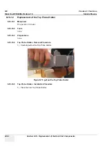
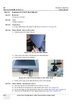
1.) Carefully pull out the Patient Monitor.
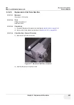
2.) Screw off the head plate of the tripot from the Patient Monitor.
3.) Screw off the tripod from the Adapter.
4.) Screw out 2 screws on the Back Handle and remove the Adapters.
8-20-10-5
Patient Monitor - Installation Procedure
5.) Insert the right and the left Adapter and fix it with the 2 screws.
6.) Fix the tripod with a thumbscrew on the Adapter (see
Figure 8-92 on page 8-70
).
7.) Fix the head plate from the tripod with a screw on the monitor (see
Figure 8-92 on page 8-70
).
8.) Place the new Patient Monitor at its original position (see
Figure 8-91 on page 8-70
).
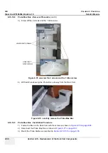
Figure 8-91 pull out the Patient Monitor
Figure 8-92 screw off the head plate / screw off the tripod
Содержание Voluson i BT06
Страница 2: ......
Страница 11: ...GE VOLUSON i VOLUSON e DIRECTION KTI106052 REVISION 10 SERVICE MANUAL ix ZH CN KO...
Страница 44: ...GE VOLUSON i VOLUSON e DIRECTION KTI106052 REVISION 10 SERVICE MANUAL xlii Table of Contents...
Страница 514: ...GE VOLUSON i VOLUSON e DIRECTION KTI106052 REVISION 10 SERVICE MANUAL IV Index...
Страница 515: ......

