CHAPTER 7: MONITORING
RTD TEMPERATURE
850 FEEDER PROTECTION SYSTEM – INSTRUCTION MANUAL
7–47
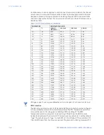
temperature. The Alarm temperature is set slightly above the normal measured
temperature for the transformer top-oil, bottom-oil, or LTC oil. The Trip temperature is
normally set at the maximum permissible oil temperatures defined as dangerous for the
transformer and the transformer insulation.
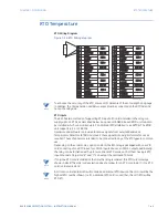
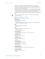
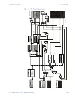
This element also monitors the RTD broken connection and blocks the RTD trip and alarm
functions if the RTD connection is detected as Open or Shorted and generates RTD Open
and RTD Shorted FlexLogic operands. An RTD is detected as Open when the RTD
connection is either open or the temperature is greater than 250°C. An RTD is detected as
Shorted when the RTD connection is either shorted or the temperature is equal to less than
-40°C.
NOTE
NOTE:
The RTD input is active regardless of whether or not, the RTD Trip, or/and RTD Alarm
functions are enabled.
Path:
Setpoints > RTD Temperature > RTD 1[X]
Path:
Setpoints > RRTD Temperature > RRTD 1[X]
TRIP FUNCTION
Range: Disabled, Trip, Configurable
Default: Disabled
If a trip is not required from the RTD, select “Configurable”. The “Configurable” setting
enables the RTD without producing a trip.
NAME
Range: Up to 13 alphanumeric characters
Default: RTD 1
TYPE
Range: 100
Ω
Platinum, 100
Ω
Nickel, 120
Ω
Nickel
Default: 100
Ω
Platinum
Selects the type of the RTD used.
TRIP TEMPERATURE
Range: 1°C to 250°C in steps of 1°C (33°F to 482°F in steps of 2°F)
Default: 155°C (311°F)
TRIP PICKUP DELAY
Range: 0 s to 600 s in steps of 1 s
Default: 2 s
TRIP DROPOUT DELAY
Range: 0 s to 600 s in steps of 1s
Default: 0 s
TRIP OUTPUT RELAY X
For details see
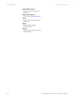
ALARM FUNCTION
Range: Disabled, Alarm, Latched Alarm
Default: Disabled
ALARM TEMPERATURE
Range: 1°C to 250°C in steps of 1°C (33°F to 482°F in steps of 2°F)
Default: 130°C (266°F)
ALARM PICKUP DELAY
Range: 0 s to 600 s in steps of 1 s
Default: 2 s
Содержание Multilin 850
Страница 10: ...VIII 850 FEEDER PROTECTION SYSTEM INSTRUCTION MANUAL ...
Страница 135: ...CHAPTER 3 INTERFACES SOFTWARE INTERFACE 850 FEEDER PROTECTION SYSTEM INSTRUCTION MANUAL 3 41 ...
Страница 151: ...CHAPTER 3 INTERFACES SOFTWARE INTERFACE 850 FEEDER PROTECTION SYSTEM INSTRUCTION MANUAL 3 57 ...
Страница 153: ...CHAPTER 3 INTERFACES SOFTWARE INTERFACE 850 FEEDER PROTECTION SYSTEM INSTRUCTION MANUAL 3 59 ...
Страница 268: ...5 106 850 FEEDER PROTECTION SYSTEM INSTRUCTION MANUAL OUTPUTS CHAPTER 5 DEVICE SYSTEM INPUT AND OUTPUT SETPOINTS ...
Страница 420: ...6 152 850 FEEDER PROTECTION SYSTEM INSTRUCTION MANUAL FREQUENCY ELEMENTS CHAPTER 6 PROTECTION SETPOINTS ...
Страница 439: ...CHAPTER 7 MONITORING FUNCTIONS 850 FEEDER PROTECTION SYSTEM INSTRUCTION MANUAL 7 19 ...
Страница 644: ...11 20 850 FEEDER PROTECTION SYSTEM INSTRUCTION MANUAL FLEXELEMENTS CHAPTER 11 METERING ...

