5–44
850 FEEDER PROTECTION SYSTEM – INSTRUCTION MANUAL
DEVICE
CHAPTER 5: DEVICE, SYSTEM, INPUT AND OUTPUT SETPOINTS
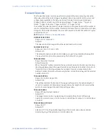
The EnerVista 8 Series Setup software is required to view all captured data. The relay
faceplate display can be used to view the date and time of trigger, the fault type and the
distance location of the fault.
Path
:
Setpoints > Device > Fault Report
FUNCTION
Range: Disabled, Enabled
Default: Disabled
PRE-FAULT TRIGGER
Range: Off, Any FlexLogic operand
Default: Off
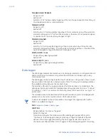
This setpoint specifies the FlexLogic operand to capture the pre-fault data. The rising
edge of this operand stores one cycle-old data for subsequent reporting. The element
waits for the fault trigger to actually create a record as long as the operand selected as
PRE-FAULT TRIGGER is “On”. If the operand remains “Off” for 1 second, the element resets
and no record is created.
FAULT TRIGGER
Range: Off, Any FlexLogic operand
Default: Off
This setpoint specifies the FlexLogic operand to capture the fault data. The rising edge of
this operand stores the data as fault data and results in a new report. The trigger (not the
pre-fault trigger) controls the date and time of the report. The distance to fault
calculations are initiated by this signal.
UNITS OF LENGTH
Range: km, Miles
Default: km
This setting provides the units of measurement, in kilometers or miles.
LENGTH OF FEEDER
Range: 0.1 to 99.9 km/Miles in steps of 0.1 km/Miles
Default: 0.1 km/Miles
This setting provides the total length of the feeder, in kilometers or miles as selected by
the UNITS OF LENGTH setpoint.
Z_1 (RESISTIVE/INDUCTIVE) OF FEEDER
Range: 0.01 to 250.00
Ω
in steps of 0.01
Ω
Default: 0.01
Ω
This setting sets the total real/imaginary component of the feeder positive sequence
impedance, in secondary ohms.
Z_0 (RESISTIVE/INDUCTIVE) OF FEEDER
Range: 0.01 to 650.00
Ω
in steps of 0.01
Ω
Default: 0.01
Ω
This setting sets the total real/imaginary component of the feeder zero sequence
impedance, in secondary ohms.
VT SUBSTITUTION
Range: None, I0, V0
Default: None
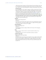
This setting is set to
None
if the relay is fed from wye-connected VTs. If delta-connected
VTs are used, and the relay is supplied with the neutral (3V0) voltage, this setting should
be set to
V0
. The method is still exact, as the fault locator would combine the line-to-line
voltage measurements with the neutral voltage measurement to re-create the line-to-
ground voltages. It is required to configure the delta and neutral voltages under the
Содержание Multilin 850
Страница 10: ...VIII 850 FEEDER PROTECTION SYSTEM INSTRUCTION MANUAL ...
Страница 135: ...CHAPTER 3 INTERFACES SOFTWARE INTERFACE 850 FEEDER PROTECTION SYSTEM INSTRUCTION MANUAL 3 41 ...
Страница 151: ...CHAPTER 3 INTERFACES SOFTWARE INTERFACE 850 FEEDER PROTECTION SYSTEM INSTRUCTION MANUAL 3 57 ...
Страница 153: ...CHAPTER 3 INTERFACES SOFTWARE INTERFACE 850 FEEDER PROTECTION SYSTEM INSTRUCTION MANUAL 3 59 ...
Страница 268: ...5 106 850 FEEDER PROTECTION SYSTEM INSTRUCTION MANUAL OUTPUTS CHAPTER 5 DEVICE SYSTEM INPUT AND OUTPUT SETPOINTS ...
Страница 420: ...6 152 850 FEEDER PROTECTION SYSTEM INSTRUCTION MANUAL FREQUENCY ELEMENTS CHAPTER 6 PROTECTION SETPOINTS ...
Страница 439: ...CHAPTER 7 MONITORING FUNCTIONS 850 FEEDER PROTECTION SYSTEM INSTRUCTION MANUAL 7 19 ...
Страница 644: ...11 20 850 FEEDER PROTECTION SYSTEM INSTRUCTION MANUAL FLEXELEMENTS CHAPTER 11 METERING ...

