5–34
850 FEEDER PROTECTION SYSTEM – INSTRUCTION MANUAL
DEVICE
CHAPTER 5: DEVICE, SYSTEM, INPUT AND OUTPUT SETPOINTS
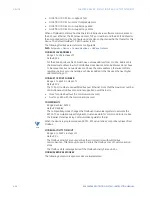
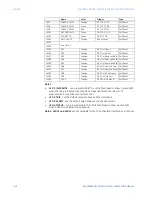
The IEC 60870-5-104 Deadbands settings are used to determine when to trigger
spontaneous responses containing M_ME_NB_1 analog data. Each setting represents the
threshold value for each M_ME_NB_1 analog point.
For example, to trigger spontaneous responses from the 850 when a current value
changes by 15 A, the “Analog Point xx Deadband” setting should be set to 15. Note that
these settings are the default values of the deadbands. P_ME_NB_1 (parameter of
measured value, scaled value) points can be used to change threshold values, from the
default, for each individual M_ME_NB_1 analog point. There are three ways to send the
measurands to the Master station. The measurands are part of the General Group and
Group 2, so when a general interrogation or group 2 interrogation takes place all the
measurands are included in the response. Also, there is a cyclic data period setting where
it is configured in the scan period to send the measurands to the Master. And the last way,
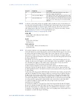
is by sending spontaneously when a deadband overflow takes place. The IEC104 Channels
sub-menu information is shown below.
Commands are executed over the Binary Outputs. The first 8 Binary Outputs are
configured to receive Select/Operate Commands and the next 8 Binary Outputs are
configured to receive Direct Execute Commands.
The
IEC104 CHANNEL 1 PORT
and
IEC104 CHANNEL 2 PORT
settings select the
communications port assigned to the IEC104 protocol for each channel. When this setting
is set to “Network - TCP”, the IEC104 protocol can be used over TCP/IP on channels 1 or 2.
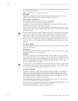
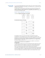
The
IEC104 NETWORK CLIENT ADDRESS
settings can force the 850 to respond to a
maximum of two specific IEC104 masters which own the configured IP Addresses. The
settings in this sub-menu are shown below.
FASTPATH:
“IEC104 Channel 1 Port” takes the “Port Number 1” and “Client Address 1” to allow or reject
connections. The same method is used by channel 2.
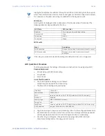
GROUPS OF DATA
The data is organized into groups in order to provide values when the controlling station
requests them by a general or group interrogation.
Group 1 is set by the 96 Single Points (M_SP).
Group 2 is set by the 32 Measured values (M_ME).
Group 3 is set by the 32 Measured thresholds (P_ME).
These 96 Single Points and 32 Measured Values are also sent as a response to a General
Interrogation.
The Integrated Totals (M_IT) has its own Counter Group 1, and it is sent as a response to a
General Request Counter.
Содержание Multilin 850
Страница 10: ...VIII 850 FEEDER PROTECTION SYSTEM INSTRUCTION MANUAL ...
Страница 135: ...CHAPTER 3 INTERFACES SOFTWARE INTERFACE 850 FEEDER PROTECTION SYSTEM INSTRUCTION MANUAL 3 41 ...
Страница 151: ...CHAPTER 3 INTERFACES SOFTWARE INTERFACE 850 FEEDER PROTECTION SYSTEM INSTRUCTION MANUAL 3 57 ...
Страница 153: ...CHAPTER 3 INTERFACES SOFTWARE INTERFACE 850 FEEDER PROTECTION SYSTEM INSTRUCTION MANUAL 3 59 ...
Страница 268: ...5 106 850 FEEDER PROTECTION SYSTEM INSTRUCTION MANUAL OUTPUTS CHAPTER 5 DEVICE SYSTEM INPUT AND OUTPUT SETPOINTS ...
Страница 420: ...6 152 850 FEEDER PROTECTION SYSTEM INSTRUCTION MANUAL FREQUENCY ELEMENTS CHAPTER 6 PROTECTION SETPOINTS ...
Страница 439: ...CHAPTER 7 MONITORING FUNCTIONS 850 FEEDER PROTECTION SYSTEM INSTRUCTION MANUAL 7 19 ...
Страница 644: ...11 20 850 FEEDER PROTECTION SYSTEM INSTRUCTION MANUAL FLEXELEMENTS CHAPTER 11 METERING ...

