6–20
850 FEEDER PROTECTION SYSTEM – INSTRUCTION MANUAL
CURRENT ELEMENTS
CHAPTER 6: PROTECTION SETPOINTS
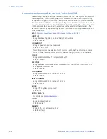
Neutral Time Overcurrent Protection (51N)
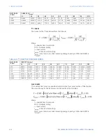
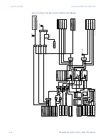
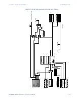
The 850 computes the neutral current (In) using the following formula:
|In|=|Ia+Ib+Ic|
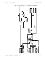
The settings of this function are applied to the neutral current to produce Trip or Pickup
flags. The Neutral TOC Pickup flag is asserted when the neutral current is above the PKP
value. The Neutral TOC Trip flag is asserted if the element stays picked up for the time
defined by the selected inverse curve and the magnitude of the current. The element
drops from Pickup without operation if the measured current drops below 97 to 98% of the
Pickup value before the time for operation is reached. When Definite Time is selected, the
time for Neutral TOC operation is defined only by the TDM setting.
Path
:
Setpoints > Protection > Group 1(6) > Current > Neutral TOC 1(X)
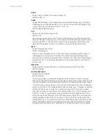
FUNCTION
Range: Disabled, Trip, Alarm, Latched Alarm, Configurable
Default: Disabled
SIGNAL INPUT
Range: dependant upon the order code
Default: CT Bank 1-J1
This setting provides the selection for the current input bank. The default bank names
can be changed in: Setpoints > System > Current Sensing > [Name] > CT Bank Name.
INPUT
Range: Phasor, RMS
Default: Phasor
This selection defines the method of processing of the current signal. It could be Root
Mean Square (RMS) or Fundamental Phasor Magnitude.
PICKUP
Range: 0.050 to 30.000 x CT in steps of 0.001 x CT
Default: 1.000 x CT
CURVE
Range: IEEE Extremely/Very/Moderately Inverse
ANSI Extremely/Very/Normally/Moderately Inverse
Definite time
IEC A/B/C and Short Inverse
IAC Extremely/Very/Inverse/Short Inverse
FlexCurve A/B/C/D, I2t, I4t
Default: IEEE Moderately Inverse
This setting sets the shape of the selected over-current inverse curve. If none of the
standard curve shapes is appropriate, a FlexCurve can be created. Refer to the User
curve and the FlexCurve setup for more details on their configurations and usage.
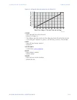
TDM
Range: 0.05 to 600.00 in steps of 0.01
Default: 1.00
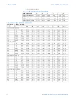
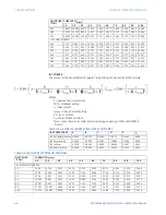
This setting provides selection of the Time Dial Multiplier by which the times from the
inverse curve are modified. For example if an ANSI Extremely Inverse curve is selected
with TDM = 2, and the fault current is 5 times bigger than the PKP level, the operation of
the element will not occur until 2.59s of time has elapsed from pickup.
Содержание Multilin 850
Страница 10: ...VIII 850 FEEDER PROTECTION SYSTEM INSTRUCTION MANUAL ...
Страница 135: ...CHAPTER 3 INTERFACES SOFTWARE INTERFACE 850 FEEDER PROTECTION SYSTEM INSTRUCTION MANUAL 3 41 ...
Страница 151: ...CHAPTER 3 INTERFACES SOFTWARE INTERFACE 850 FEEDER PROTECTION SYSTEM INSTRUCTION MANUAL 3 57 ...
Страница 153: ...CHAPTER 3 INTERFACES SOFTWARE INTERFACE 850 FEEDER PROTECTION SYSTEM INSTRUCTION MANUAL 3 59 ...
Страница 268: ...5 106 850 FEEDER PROTECTION SYSTEM INSTRUCTION MANUAL OUTPUTS CHAPTER 5 DEVICE SYSTEM INPUT AND OUTPUT SETPOINTS ...
Страница 420: ...6 152 850 FEEDER PROTECTION SYSTEM INSTRUCTION MANUAL FREQUENCY ELEMENTS CHAPTER 6 PROTECTION SETPOINTS ...
Страница 439: ...CHAPTER 7 MONITORING FUNCTIONS 850 FEEDER PROTECTION SYSTEM INSTRUCTION MANUAL 7 19 ...
Страница 644: ...11 20 850 FEEDER PROTECTION SYSTEM INSTRUCTION MANUAL FLEXELEMENTS CHAPTER 11 METERING ...

