5–20
850 FEEDER PROTECTION SYSTEM – INSTRUCTION MANUAL
DEVICE
CHAPTER 5: DEVICE, SYSTEM, INPUT AND OUTPUT SETPOINTS
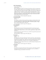
•
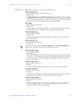
FUNCTION CODE 08H - Loopback Test
•
FUNCTION CODE 10H - Store Multiple Setpoints
•
FUNCTION CODE 42H - Group Settings Read
•
FUNCTION CODE 43H - Group Settings Write
When a ModBus master such as the EnerVista 8 Series Setup software communicates to
the 850 over Ethernet, the 850 slave address, TCP port number and the 850 IP address for
the associated port must be configured and are also configured within the Master for this
device. The default ModBus TCP port number is 502.
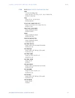
The following ModBus parameters are configurable:
Path:
Setpoints > Device > Communications > Modbus Protocol
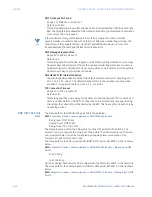
MODBUS SLAVE ADDRESS
Range: 1 to 254 in steps of 1
Default: 254
For the RS485 ports each 850 must have a unique address from 1 to 254. Address 0 is
the broadcast address to which all Modbus slave devices listen. Addresses do not have
to be sequential, but no two devices can have the same address, otherwise conflicts
resulting in errors occur. Generally, each device added to the link uses the next higher
address starting at 1.
MODBUS TCP PORT NUMBER
Range: 1 to 65535 in steps of 1
Default: 502
The TCP port number used with Modbus over Ethernet. Note that the maximum number
of simultaneous Modbus connections supported over Ethernet is:
•
three for an 850 without the communications card,
•
five for an 850 with the communications card.
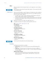
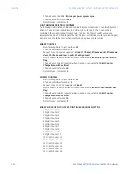
COMPATIBILITY
Range: Disabled, SR750
Default: Disabled
The Compatibility mode changes the Modbus actual value registers to emulate the
SR750. The emulation supports typical actual value data for common data items. See
the
8 Series Protective Relay Communications guide
for the list.
NOTE
NOTE:
When the device is programmed as a SR750, 850 actual values cannot be retrieved from
Modbus.
MODBUS ACTIVITY TIMEOUT
Range: 0 to 3600 s in steps of 1
Default: 0 s
The Modbus Activity Timeout specifies the minimum time without Modbus
communication. This timeout is used to declare the Modbus ‘Loss of Communication’
state.
The Modbus state is always Active if the Modbus Activity Timeout is 0 s.
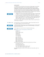
MODBUS ERROR RESPONSES
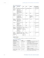
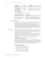
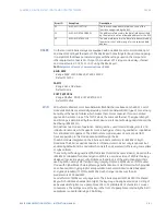
The following exception response codes are implemented.
Содержание Multilin 850
Страница 10: ...VIII 850 FEEDER PROTECTION SYSTEM INSTRUCTION MANUAL ...
Страница 135: ...CHAPTER 3 INTERFACES SOFTWARE INTERFACE 850 FEEDER PROTECTION SYSTEM INSTRUCTION MANUAL 3 41 ...
Страница 151: ...CHAPTER 3 INTERFACES SOFTWARE INTERFACE 850 FEEDER PROTECTION SYSTEM INSTRUCTION MANUAL 3 57 ...
Страница 153: ...CHAPTER 3 INTERFACES SOFTWARE INTERFACE 850 FEEDER PROTECTION SYSTEM INSTRUCTION MANUAL 3 59 ...
Страница 268: ...5 106 850 FEEDER PROTECTION SYSTEM INSTRUCTION MANUAL OUTPUTS CHAPTER 5 DEVICE SYSTEM INPUT AND OUTPUT SETPOINTS ...
Страница 420: ...6 152 850 FEEDER PROTECTION SYSTEM INSTRUCTION MANUAL FREQUENCY ELEMENTS CHAPTER 6 PROTECTION SETPOINTS ...
Страница 439: ...CHAPTER 7 MONITORING FUNCTIONS 850 FEEDER PROTECTION SYSTEM INSTRUCTION MANUAL 7 19 ...
Страница 644: ...11 20 850 FEEDER PROTECTION SYSTEM INSTRUCTION MANUAL FLEXELEMENTS CHAPTER 11 METERING ...

