7–38
850 FEEDER PROTECTION SYSTEM – INSTRUCTION MANUAL
HARMONIC DETECTION
CHAPTER 7: MONITORING
Harmonic Detection
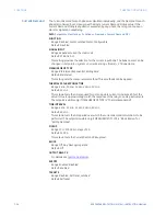
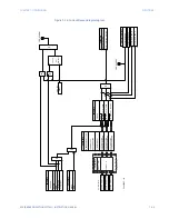
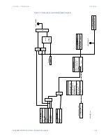
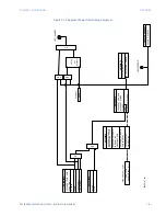
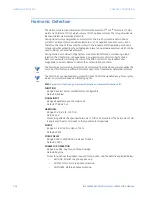
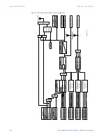
The Harmonic detection 1(6) element monitors the selected 2
nd
to 5
th
harmonic or Total
Harmonics Distortion (THD), which is present in the phase currents. The relay provides six
identical Harmonic Detection elements.
During transformer energization or motor starts, the inrush current present in phase
currents can impact some sensitive elements, such as negative sequence overcurrent.
Therefore, the ratio of the second harmonic to the fundamental magnitude per phase is
monitored, while exceeding the settable pickup level, an operand is asserted, which can be
used to block such sensitive elements.
During startup or shutdown of generator connected transformers, or following a load
rejection, the transformer can experience an excessive ratio of volts to hertz, that is,
become overexcited. Similarly, the ratio of the fifth harmonic to the fundamental
magnitude can be monitored to detect the overexcitation condition.
NOTE
NOTE:
The harmonics monitored in this element is calculated from the phase currents, unlike the
second or fifth harmonic differential current used in the transformer differential element.
NOTE
NOTE:
The harmonics are updated every protection pass. The THD is updated every three cycles,
which is not recommended as a blocking signal.
Path
:
Setpoints > Monitoring > Harmonic Detection > Harmonic Detection 1(X)
FUNCTION
Range: Disabled, Alarm, Latched Alarm, Configurable
Default: Disabled
SIGNAL INPUT
Range: dependant upon the order code
Default: CT Bank 1–J1
HARMONIC
Range: 2nd, 3rd, 4th, 5th, THD
Default: 2nd
This setting selects the specified harmonic or THD to be monitored. The harmonic or THD
is expressed in percent relative to the fundamental magnitude.
PICKUP
Range: 0.1 to 100.0% in steps of 0.1%
Default: 20.0%
PICKUP DELAY
Range: 0.000 to 60000.000 s in steps of 0.001 s
Default: 0.000 s
PHASES FOR OPERATION
Range: Any One, Any Two, All Three, Average
Default: Any One
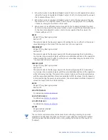
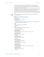
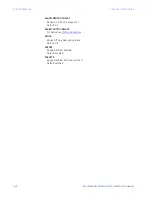
This setting defines the phases required for operation, and the detail is explained below:
–
ANY ONE: At least one phase picked up.
–
ANY TWO: Two or more phases picked up.
–
ANY THREE: All three phases picked up.
Содержание Multilin 850
Страница 10: ...VIII 850 FEEDER PROTECTION SYSTEM INSTRUCTION MANUAL ...
Страница 135: ...CHAPTER 3 INTERFACES SOFTWARE INTERFACE 850 FEEDER PROTECTION SYSTEM INSTRUCTION MANUAL 3 41 ...
Страница 151: ...CHAPTER 3 INTERFACES SOFTWARE INTERFACE 850 FEEDER PROTECTION SYSTEM INSTRUCTION MANUAL 3 57 ...
Страница 153: ...CHAPTER 3 INTERFACES SOFTWARE INTERFACE 850 FEEDER PROTECTION SYSTEM INSTRUCTION MANUAL 3 59 ...
Страница 268: ...5 106 850 FEEDER PROTECTION SYSTEM INSTRUCTION MANUAL OUTPUTS CHAPTER 5 DEVICE SYSTEM INPUT AND OUTPUT SETPOINTS ...
Страница 420: ...6 152 850 FEEDER PROTECTION SYSTEM INSTRUCTION MANUAL FREQUENCY ELEMENTS CHAPTER 6 PROTECTION SETPOINTS ...
Страница 439: ...CHAPTER 7 MONITORING FUNCTIONS 850 FEEDER PROTECTION SYSTEM INSTRUCTION MANUAL 7 19 ...
Страница 644: ...11 20 850 FEEDER PROTECTION SYSTEM INSTRUCTION MANUAL FLEXELEMENTS CHAPTER 11 METERING ...

