6–38
850 FEEDER PROTECTION SYSTEM – INSTRUCTION MANUAL
CURRENT ELEMENTS
CHAPTER 6: PROTECTION SETPOINTS
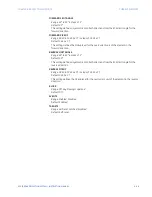
POLARIZING MODE
Range: Voltage, Current, Dual
Default: Voltage
This setting selects the polarizing mode for the directional unit.
•
If
Voltage
polarizing mode is selected, the element uses the zero-sequence voltage
angle for polarization. Select either the zero-sequence voltage V_0, calculated from
the phase voltages, or the zero-sequence voltage supplied externally as the auxiliary
voltage V_X.
The calculated V_0 can be used as polarizing voltage only if the voltage transformers
are connected in Wye. The auxiliary voltage can be used as the polarizing voltage if
the auxiliary voltage is connected to a zero-sequence voltage source (such as the
open delta connected secondary of VTs).
The zero-sequence (V_0) or auxiliary voltage (Vx), accordingly, must be greater than
the voltage set under "Polarizing Volt Supv" to be validated for use as a polarizing
signal. If the polarizing signal is invalid, neither forward nor reverse indication is given.
•
If
Current
polarizing mode is selected, the element uses the angle of the polarizing
current measured on the ground current input K1-CT (if available). The polarizing
current must be greater than 0.05 x CT to be validated as a polarizing signal. If the
polarizing signal is not valid, neither forward nor reverse indication is given.
For a choice of current polarizing, it is recommended that the polarizing signal be
analyzed to ensure that a known direction is maintained irrespective of the fault
location.
NOTE
NOTE:
When signal input is J1 in the ground directional element, Current Input is J1-CT ground
current, and Polarizing current input is K1-CT ground current. When signal input is K1 for
the dual feeder 850-D, Current Input is K1-CT ground current, and Polarizing current input
is J1-CT ground current.
•
If
Dual
polarizing mode is selected, the element performs both directional
comparisons as described above. A given direction is confirmed if either voltage or
current comparators indicate so. If a conflicting (simultaneous forward and reverse)
indication occurs, the forward direction overrides the reverse direction.
POLARIZING VOLTAGE
Range: Calculated V0, Measured VX
Default: Calculated V0
Selects the polarizing voltage used by the directional unit when "Voltage" or "Dual"
polarizing mode is set. The polarizing voltage can be programmed to be either the zero-
sequence voltage calculated from the phase voltages ("Calculated V_0") or supplied
externally as an auxiliary voltage ("Measured VX")
POLARIZING VOL SUPV
Range: 0.005 to 0.100 x VT in steps of 0.005 x VT
Default: 0.020 x VT
The zero-sequence (V_0) or auxiliary voltage (Vx), accordingly, must be greater than the
Polarizing supervision voltage configured in this setting, to be validated for use as a
polarizing signal. If the polarizing signal is invalid, neither forward nor reverse indication
is given.
FORWARD ECA
Range: –90° to 90° in steps of 1°
Default: 75°
This setting defines the element characteristic angle (ECA) for the forward direction in
"Voltage" polarizing mode. "Current" polarizing mode uses a fixed ECA of 0°. The ECA in
the reverse direction is the angle set for the forward direction shifted by 180°.
Содержание Multilin 850
Страница 10: ...VIII 850 FEEDER PROTECTION SYSTEM INSTRUCTION MANUAL ...
Страница 135: ...CHAPTER 3 INTERFACES SOFTWARE INTERFACE 850 FEEDER PROTECTION SYSTEM INSTRUCTION MANUAL 3 41 ...
Страница 151: ...CHAPTER 3 INTERFACES SOFTWARE INTERFACE 850 FEEDER PROTECTION SYSTEM INSTRUCTION MANUAL 3 57 ...
Страница 153: ...CHAPTER 3 INTERFACES SOFTWARE INTERFACE 850 FEEDER PROTECTION SYSTEM INSTRUCTION MANUAL 3 59 ...
Страница 268: ...5 106 850 FEEDER PROTECTION SYSTEM INSTRUCTION MANUAL OUTPUTS CHAPTER 5 DEVICE SYSTEM INPUT AND OUTPUT SETPOINTS ...
Страница 420: ...6 152 850 FEEDER PROTECTION SYSTEM INSTRUCTION MANUAL FREQUENCY ELEMENTS CHAPTER 6 PROTECTION SETPOINTS ...
Страница 439: ...CHAPTER 7 MONITORING FUNCTIONS 850 FEEDER PROTECTION SYSTEM INSTRUCTION MANUAL 7 19 ...
Страница 644: ...11 20 850 FEEDER PROTECTION SYSTEM INSTRUCTION MANUAL FLEXELEMENTS CHAPTER 11 METERING ...

