8–102
850 FEEDER PROTECTION SYSTEM – INSTRUCTION MANUAL
CT SUPERVISION
CHAPTER 8: CONTROL
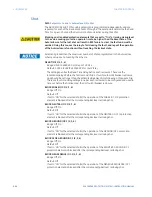
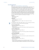
SEQ 3V0 PKP
Range: 0.02 to 3.00 x VT in steps of 0.01
Default: 0.20 x VT
This setting is part of the sequence check and it represents the threshold for zero
sequence voltage measurement. This zero sequence voltage is calculated from the set
of 3 phase VTs.
FASTPATH:
The VTs must be connected in wye configuration in order to calculate the zero sequence
voltage.
SEQ IG PKP
Range: 0.050 to 30.000 x CT in steps of 0.001
Default: 0.200 x CT
This setting is part of the sequence check and it represents the threshold for the
measured ground current. The ground current must be a separate input. It should not be
connected in the residual ground connection method for this check to function. Refer to
the Sequence Check Ground Inputs figure for more information.
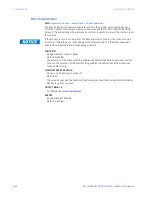
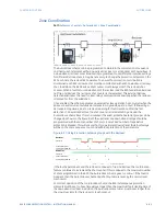
CTS detection using the Differential Check Method
DIFFERENTIAL CHECK
Range: Disabled, Enabled
Default: Disabled
This setting enables the differential check function. The differential check uses zero
sequence current and measured ground current.
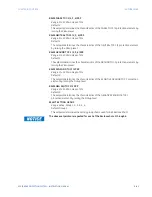
DIFF CURRENT PKP
Range: 0.050 to 30.000 x CT in steps of 0.001
Default: 0.500 x CT
This setting represents the threshold for the differential current calculated between the
calculated zero sequence current and the measured ground current from a core balance
CT. If the differential current magnitude is higher than the pickup value, the differential
check operates.
DIFF SLOPE
Range: 0 to 100% in steps of 1
Default: 10%
The slope setting is a ratio between the maximum current measured and the differential
current above the pickup value. This setting allows for CT error tolerances as the load
currents increase. Steeper slope means higher tolerances. By using the slope setting, the
pickup value can be automatically increased according to the increasing total current
difference. This setting can be set to 0 if correction to the pickup value is not required
under higher current loading.
DIFF IG POLARITY
Range: Same, Reverse
Default: Same
If during commissioning, it is discovered that the core balance CT polarity is reverse, this
setting can be used to change the polarity. This setting only applies to the differential
check portion of the element. Other elements in the relay will remain unaffected.
FASTPATH:
Refer to the Differential Check Ground Inputs figure for additional grounding information
and CT polarity setting.
Содержание Multilin 850
Страница 10: ...VIII 850 FEEDER PROTECTION SYSTEM INSTRUCTION MANUAL ...
Страница 135: ...CHAPTER 3 INTERFACES SOFTWARE INTERFACE 850 FEEDER PROTECTION SYSTEM INSTRUCTION MANUAL 3 41 ...
Страница 151: ...CHAPTER 3 INTERFACES SOFTWARE INTERFACE 850 FEEDER PROTECTION SYSTEM INSTRUCTION MANUAL 3 57 ...
Страница 153: ...CHAPTER 3 INTERFACES SOFTWARE INTERFACE 850 FEEDER PROTECTION SYSTEM INSTRUCTION MANUAL 3 59 ...
Страница 268: ...5 106 850 FEEDER PROTECTION SYSTEM INSTRUCTION MANUAL OUTPUTS CHAPTER 5 DEVICE SYSTEM INPUT AND OUTPUT SETPOINTS ...
Страница 420: ...6 152 850 FEEDER PROTECTION SYSTEM INSTRUCTION MANUAL FREQUENCY ELEMENTS CHAPTER 6 PROTECTION SETPOINTS ...
Страница 439: ...CHAPTER 7 MONITORING FUNCTIONS 850 FEEDER PROTECTION SYSTEM INSTRUCTION MANUAL 7 19 ...
Страница 644: ...11 20 850 FEEDER PROTECTION SYSTEM INSTRUCTION MANUAL FLEXELEMENTS CHAPTER 11 METERING ...

