10 Specifications and Theory of Operation
M1132382
10-19
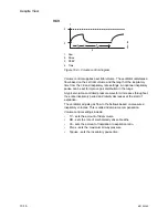
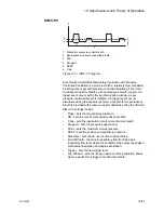
PSVPro
1. Paw
2. PEEP
3. Time
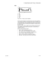
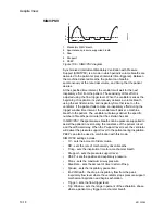
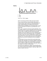
Figure 10-6 • PSVPro diagram
PSVPro is pressure supported ventilation with apnea backup.
PSVPro is a spontaneous mode of ventilation that provides a
constant pressure once the ventilator senses that the patient has
made an inspiratory effort. In this mode, the clinician sets the
Pressure Support (Psupport) and PEEP levels. The patient
establishes the rate, inspiratory flow, and inspiratory time. The tidal
volume is determined by the pressure, lung characteristics, and
patient effort.
PSVPro uses an inspiration termination level that establishes when
the ventilator will stop the pressure supported breath and cycle to the
expiratory phase. The inspiration termination level is user adjustable
from 5% to 50%. This parameter sets the percent of the peak
inspiratory flow that the ventilator uses to end the inspiratory phase of
the breath and to cycle into the expiratory phase. If the inspiration
termination is set to 30% then the ventilator will stop inspiration when
the flow decelerates to a level equal to 30% of the measured peak
inspiratory flow. The lower the setting the longer the inspiratory time
and conversely, the higher the setting the shorter the inspiratory
phase.
An apnea backup mode is provided in the event the patient stops
breathing. When setting this mode the clinician adjusts the inspiratory
pressure (Pinsp), respiratory rate, and the inspiratory time (Tinsp). As
long as the patient is triggering the ventilator and the apnea alarm
does not activate, the patient will get pressure-supported breaths and
the ventilator will not deliver machine breaths.
If the patient stops triggering the ventilator for the set apnea delay
time, the apnea alarm will activate and the ventilator will automatically
switch to the backup mode that is SIMV-PC mode. See “
” for
operation details for this mode.
T
I
AB
.9
1
.04
1
1
2
3
Содержание Aespire View
Страница 1: ...Aespire View User s Reference Manual Software Revision 6 X...
Страница 16: ...Aespire View 1 8 M1132382...
Страница 46: ...Aespire View 3 16 M1132382...
Страница 50: ...Aespire View 4 4 M1132382...
Страница 88: ...Aespire View 7 8 M1132382...
Страница 112: ...Aespire View 9 10 M1132382...
Страница 114: ...Aespire View 10 2 M1132382 System pneumatic circuits Figure 10 1 Pneumatic circuit diagram AC 20 001...
Страница 118: ...Aespire View 10 6 M1132382 Electrical block diagram Figure 10 2 Electrical block diagram AC 20 008...
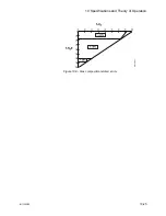
Страница 137: ...10 Specifications and Theory of Operation M1132382 10 25 Figure 10 9 Gas composition related errors AB 74 027...
Страница 148: ...Aespire View I 4 M1132382...

