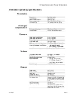


10 Specifications and Theory of Operation
M1132382
10-29
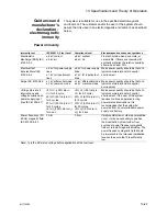
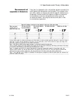
Recommended
separation distances
The system is intended for use in the electromagnetic environment in
which radiated RF disturbances are controlled. The customer or the
user of the system can help prevent electromagnetic interference by
maintaining a minimum distance between portable and mobile RF
communications equipment (transmitters) and the system as
recommended below, according tho the maximum power of the
communications equipment.
Separation distance in meters (m) according to frequency of the transmitter
Rated maximum
output power of
transmitter watts (W)
150 kHz to 80 MHz
Outside ISM bands
150 kHz to 80 MHz In
ISM bands
80 MHz to 800 MHz
800 MHz to 2.5 GHz
0.01
0.35
1.2
0.12
0.23
0.1
1.1
3.8
0.38
0.73
1
3.5
12
1.2
2.3
10
11
38
3.8
7.3
100
35
120
12
23
For transmitters rated at a maximum output power not listed above, the recommended separation distance D in meters (m) can be
determined using the equation applicable to the frequency of the transmitter, where P is the maximum output power rating of the
transmitter in watts (W) according to the transmitter manufacturer.
Note 1: At 80 MHz to 800 MHz the separation distance for the higher frequency range applies.
Note 2: The ISM (Industrial, Scientific and Medical) bands between 150 kHz and 80 MHz are 6.765 MHz to 6.795 MHz; 13.553 MHz
to 13.567 MHz; 26.957 MHz to 27.283 MHz; and 40.66 MHz to 40.70 MHz.
Note 3: An additional factor of 10/3 is used in calculating the recommended separation distance for transmitters in the ISM
frequency bands between 150 kHz and 80 MHz and in the frequency range 80 MHz to 2.5 GHz to decrease the likelihood that
mobile/portable communications equipment could cause interference if it is inadvertently brought into patient areas.
Note 4: These guidelines may not apply in all situations. Electromagnetic propagation is affected by absorption and reflection from
structures, objects, and people.
Содержание Aespire View
Страница 1: ...Aespire View User s Reference Manual Software Revision 6 X...
Страница 16: ...Aespire View 1 8 M1132382...
Страница 46: ...Aespire View 3 16 M1132382...
Страница 50: ...Aespire View 4 4 M1132382...
Страница 88: ...Aespire View 7 8 M1132382...
Страница 112: ...Aespire View 9 10 M1132382...
Страница 114: ...Aespire View 10 2 M1132382 System pneumatic circuits Figure 10 1 Pneumatic circuit diagram AC 20 001...
Страница 118: ...Aespire View 10 6 M1132382 Electrical block diagram Figure 10 2 Electrical block diagram AC 20 008...
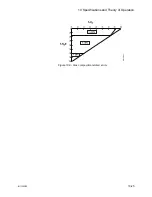
Страница 137: ...10 Specifications and Theory of Operation M1132382 10 25 Figure 10 9 Gas composition related errors AB 74 027...
Страница 148: ...Aespire View I 4 M1132382...