


10 Specifications and Theory of Operation
M1132382
10-27
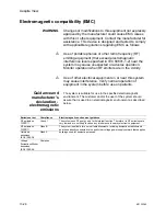
Guidance and
manufacturer’s
declaration -
electromagnetic
immunity
The system is suitable for use in the specified electromagnetic
environment. The customer and/or the user of the system should
assure that it is used in an electromagnetic environment as described
below.
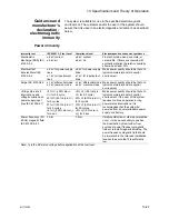
Power immunity
Immunity test
IEC 60601-1-2 test Level
Compliance level
Electromagnetic environment guidance
Electrostatic
discharge (ESD) IEC
61000-4-2
± 6 kV contact
± 8 kV air
± 6 kV contact
± 8 kV air
Floors should be wood, concrete, or
ceramic tile. If floors are covered with
synthetic material, the relative humidity
should be at least 30%.
Electrical fast
transient/burst IEC
61000-4-4
± 2 kV for power supply
lines
± 1 kV for input/output
lines
± 2 kV for power supply
lines
± 1 kV for input/output
lines
Mains power quality should be that of a
typical commercial and/or hospital
environment.
Surge IEC 61000-4-5 ± 1 kV differential mode
± 2 kV common mode
± 1 kV differential mode
± 2 kV common mode
Mains power quality should be that of a
typical commercial and/or hospital
environment.
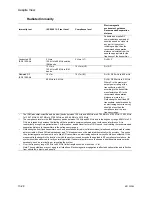
Voltage dips, short
interruptions and
voltage variations on
power supply input
lines IEC 61000-4-11
<5% U
T
(>95% dip in
U
T
) for 0.5 cycle
40% U
T
(60% dip in U
T
)
for 5 cycles
70% U
T
(30% dip in U
T
)
for 25 cycles
<5% U
T
(>95% dip in U
T
)
for 5 sec.
<5% U
T
(>95% dip in
U
T
) for 0.5 cycle)
40% U
T
(60% dip in U
T
)
for 5 cycles
70% U
T
(30% dip in U
T
)
for 25 cycles
<5% U
T
(>95% dip in
U
T
) for 5 sec.
Mains power quality should be that of a
typical commercial and/or hospital
environment. If the user of the system
requires continued operation during
power mains interruptions, it is
recommended that the system be
powered from an uninterruptible power
supply or a battery.
Power frequency (50/
60 Hz) magnetic field
IEC 61000-4-8 3
3 A/m
3 A/m
If display distortion or other abnormalities
occur, it may be necessary to position
the Anesthetic System further from
sources of power frequency magnetic
fields or to install magnetic shielding. The
power frequency magnetic field should
be immersed in the intended installation
location to assure that it is sufficiently
low.
Note: U
T
is the AC mains voltage before application of the test level.
Содержание Aespire View
Страница 1: ...Aespire View User s Reference Manual Software Revision 6 X...
Страница 16: ...Aespire View 1 8 M1132382...
Страница 46: ...Aespire View 3 16 M1132382...
Страница 50: ...Aespire View 4 4 M1132382...
Страница 88: ...Aespire View 7 8 M1132382...
Страница 112: ...Aespire View 9 10 M1132382...
Страница 114: ...Aespire View 10 2 M1132382 System pneumatic circuits Figure 10 1 Pneumatic circuit diagram AC 20 001...
Страница 118: ...Aespire View 10 6 M1132382 Electrical block diagram Figure 10 2 Electrical block diagram AC 20 008...
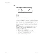
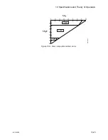
Страница 137: ...10 Specifications and Theory of Operation M1132382 10 25 Figure 10 9 Gas composition related errors AB 74 027...
Страница 148: ...Aespire View I 4 M1132382...