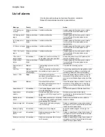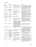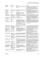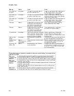
Aespire View
5-12
M1132382
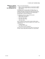
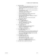
12. Test the O2 monitor and alarms (alarms other than Low O2 and
High O2 may occur).
•
Remove the O2 cell, and make sure that the cell measures
approximately 21% O2 in room air.
•
Push the Menu key.
•
Select
Alarm Setup
from the
Main Menu
.
•
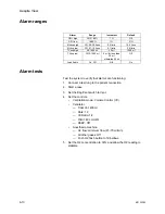
Set the Low O2 alarm to 50%, and make sure that a Low O2
alarm occurs.
•
Set the Low O2 alarm to 21%, and make sure that the Low
O2 alarm stops. This will create a latched alarm,
acknowledge this by pushing the Alarm silence key.
•
Put the O2 cell back into the circuit.
•
Set the High O2 alarm to 50%.
•
Push the O2 flush button to fill the breathing system, and
make sure that the High O2 alarm occurs.
•
Set the High O2 alarm to Off, and make sure that the alarm
stops.
•
Flow 100% O2 for 2 minutes, and make sure that the O2 cell
measures 100% O2.
13. Test the low minute volume alarm.
•
Push the Menu key.
•
Select
Alarm Setup
from the
Main Menu
.
•
Set the alarm limit for low minute volume to 6 l/min.
•
Make sure that the low minute volume alarm occurs.
•
Set the low minute volume alarm to Off.
14. Test the low airway pressure alarm.
•
Remove the test lung from the patient connection.
•
Make sure that the low airway pressure alarm occurs (other
alarms may occur).
15. Test the sustained airway pressure alarm.
•
Set the APL valve to 70 cmH2O.
•
Set the Bag/Vent switch to Bag.
•
Occlude the patient connection and push the O2 flush button.
•
Make sure that the Ppeak high. Blockage? (sustained airway
pressure) alarm occurs after approximately 15 seconds at the
sustained pressure limit.
Содержание Aespire View
Страница 1: ...Aespire View User s Reference Manual Software Revision 6 X...
Страница 16: ...Aespire View 1 8 M1132382...
Страница 46: ...Aespire View 3 16 M1132382...
Страница 50: ...Aespire View 4 4 M1132382...
Страница 88: ...Aespire View 7 8 M1132382...
Страница 112: ...Aespire View 9 10 M1132382...
Страница 114: ...Aespire View 10 2 M1132382 System pneumatic circuits Figure 10 1 Pneumatic circuit diagram AC 20 001...
Страница 118: ...Aespire View 10 6 M1132382 Electrical block diagram Figure 10 2 Electrical block diagram AC 20 008...
Страница 137: ...10 Specifications and Theory of Operation M1132382 10 25 Figure 10 9 Gas composition related errors AB 74 027...
Страница 148: ...Aespire View I 4 M1132382...

