Aespire View
5-6
M1132382
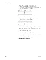
6. Test the Link-25 system by increasing the N2O flow.
•
Slowly turn the N2O flow control counterclockwise.
•
Increase the N2O flow as specified in the following table and
make sure the O2 flow is as specified.
7. Test the Link-25 system with O2 flow decreasing.
•
Set the N2O flow to 9 l/min.
•
Set the O2 flow to 3 l/min or higher.
•
Slowly turn the O2 flow control clockwise. Set the N2O flow to
the rates shown in the following table.
8. Adjust the flow of all gases through the full range and make sure
that the flow tube floats move smoothly.
9. Disconnect the O2 pipeline supply or close the O2 cylinder valve.
10. Make sure that:
•
The low O2 supply alarm occurs.
•
The N2O and the O2 flows stop. The O2 flow should stop
last.
•
The air flow continues (if equipped).
•
The gas supply alarms occur on the ventilator if the ventilator
uses O2 as the drive gas.
11. Turn all the flow controls fully clockwise for minimum flow.
12. Reconnect the O2 pipeline supply.
N2O flow l/min
O2 flow greater than l/min
0.8
0.2
2 0.5
4 1.0
10
2.5
N2O flow l/min
O2 flow greater than l/min
8
2
4 1
0.8 0.2
Содержание Aespire View
Страница 1: ...Aespire View User s Reference Manual Software Revision 6 X...
Страница 16: ...Aespire View 1 8 M1132382...
Страница 46: ...Aespire View 3 16 M1132382...
Страница 50: ...Aespire View 4 4 M1132382...
Страница 88: ...Aespire View 7 8 M1132382...
Страница 112: ...Aespire View 9 10 M1132382...
Страница 114: ...Aespire View 10 2 M1132382 System pneumatic circuits Figure 10 1 Pneumatic circuit diagram AC 20 001...
Страница 118: ...Aespire View 10 6 M1132382 Electrical block diagram Figure 10 2 Electrical block diagram AC 20 008...
Страница 137: ...10 Specifications and Theory of Operation M1132382 10 25 Figure 10 9 Gas composition related errors AB 74 027...
Страница 148: ...Aespire View I 4 M1132382...

