3 Operation
M1132382
3-3
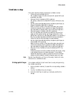
Ventilator setup
The system has the following mechanical ventilation modes:
•
Volume Control Ventilation (VCV).
The ventilator delivers the tidal volume to the patient at the set
respiratory rate (RR).
•
Pressure Control Ventilation (PCV) (optional).
The airway pressure is controlled to the value of Pinsp in every
breath.
•
Synchronized Intermittent Mandatory Ventilation with Pressure
Support Ventilation (SIMV/PSV) (optional).
Sets a minimum number of mechanical breaths using volume
control to be delivered to the patient, but allows the patient to
have spontaneous breaths which can be pressure supported.
•
Pressure Support Ventilation (PSVPro) (optional).
This is a spontaneous mode that provides the set amount of
pressure to the patient during each triggered breath or, if the
patient does not have any spontaneous breaths in a set period of
time, the ventilator transitions to SIMV-PC where it delivers a
minimum number of mechanically controlled breaths.
•
Synchronized Intermittent Mandatory Ventilation with Pressure
Control (SIMV-PC) (optional).
Sets a minimum number of mechanical breaths using pressure
control to be delivered to the patient, but allows the patient to
have spontaneous breaths which can be pressure supported.
•
Pressure Control Ventilation-Volume Guaranteed (PCV-VG)
(optional).
A tidal volume is set and the ventilator delivers that volume using
a decelerating flow and a constant pressure. The ventilator
adjusts the inspiratory pressure needed to deliver the set tidal
volume breath-by-breath so that the lowest pressure is used.
Note
See the
“Specifications and Theory of Operation”
section for more
information on ventilation modes.
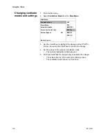
Using quick keys
The ventilator settings for each mode can be easily changed using
the ventilator quick keys.
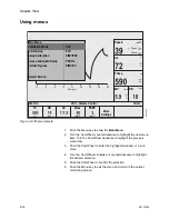
1. Push a ventilator quick key to select the corresponding ventilator
setting.
2. Turn the ComWheel to make a change.
3. Push the ComWheel or quick key to activate (confirm) the
change.
Содержание Aespire View
Страница 1: ...Aespire View User s Reference Manual Software Revision 6 X...
Страница 16: ...Aespire View 1 8 M1132382...
Страница 46: ...Aespire View 3 16 M1132382...
Страница 50: ...Aespire View 4 4 M1132382...
Страница 88: ...Aespire View 7 8 M1132382...
Страница 112: ...Aespire View 9 10 M1132382...
Страница 114: ...Aespire View 10 2 M1132382 System pneumatic circuits Figure 10 1 Pneumatic circuit diagram AC 20 001...
Страница 118: ...Aespire View 10 6 M1132382 Electrical block diagram Figure 10 2 Electrical block diagram AC 20 008...
Страница 137: ...10 Specifications and Theory of Operation M1132382 10 25 Figure 10 9 Gas composition related errors AB 74 027...
Страница 148: ...Aespire View I 4 M1132382...

