6 Alarms and Troubleshooting
M1132382
6-11
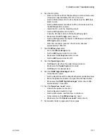
6. Test the O2 alarms.
•
Remove the O2 cell from the breathing circuit and make sure
it measures approximately 21% O2 in room air.
•
Set the
O2
low alarm limit to 50%. Make sure the
O2% low
alarm occurs.
•
Set the
O2
low alarm limit back to 21% and make sure that
the
O2% low
alarm cancels.
•
Install the O2 cell in the breathing circuit.
•
Set the
O2
high alarm limit to 50%.
•
Push the O2 flush button to fill the breathing system.
•
Make sure the
O2% high
alarm occurs.
•
Set the
O2
high alarm limit back to Off. Make sure that the
O2% high
alarm cancels.
•
After two minutes in pure O2, the O2 cell measures
approximately 100% O2.
7. Test the
MVexp low
alarm.
•
Go to the
Alarm Setup
menu.
•
Set the
MV
low alarm limit to 6.0 l/min
•
Make sure the
MVexp low
alarm occurs.
•
Set the
MV
low alarm limit to Off.
8. Test the
Ppeak high
alarm.
•
Set
Pmax
to less than the peak airway pressure.
•
Make sure the
Ppeak high
alarm occurs.
•
Set
Pmax
to the desired level.
9. Test the
PEEP high. Blockage?
alarm.
•
Close the APL valve.
•
Set the Bag/Vent switch to Bag. Mechanical ventilation stops.
•
Block the patient connection and push the O2 flush button.
•
Make sure the
PEEP high. Blockage?
alarm occurs after
approximately 15 seconds.
10. Test the
Ppeak low. Leak?
alarm.
•
Unblock the patient connection.
•
Set the Bag/Vent switch to Vent.
•
Set the tidal volume and total flow to minimum.
•
Other alarms such as
MVexp low
can occur.
•
Make sure that the
Ppeak low. Leak?
alarm occurs.
11. Set all alarm limits to approved clinical values.
Содержание Aespire View
Страница 1: ...Aespire View User s Reference Manual Software Revision 6 X...
Страница 16: ...Aespire View 1 8 M1132382...
Страница 46: ...Aespire View 3 16 M1132382...
Страница 50: ...Aespire View 4 4 M1132382...
Страница 88: ...Aespire View 7 8 M1132382...
Страница 112: ...Aespire View 9 10 M1132382...
Страница 114: ...Aespire View 10 2 M1132382 System pneumatic circuits Figure 10 1 Pneumatic circuit diagram AC 20 001...
Страница 118: ...Aespire View 10 6 M1132382 Electrical block diagram Figure 10 2 Electrical block diagram AC 20 008...
Страница 137: ...10 Specifications and Theory of Operation M1132382 10 25 Figure 10 9 Gas composition related errors AB 74 027...
Страница 148: ...Aespire View I 4 M1132382...

