Aespire View
10-14
M1132382
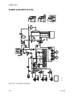
Ventilator theory
The ventilator pneumatics are located in the rear of the breathing
system. A precision flow valve controls gas flow to the patient. During
inspiration, this gas flow closes the exhalation valve and pushes the
bellows down. During expiration, a small flow pressurizes the
exhalation diaphragm to supply PEEP pressure.
Volume measurements come from flow sensors in the flow sensor
module. Two tubes from each sensor connect to a transducer. The
transducer measures the pressure change across each sensor,
which changes with the flow. A third pressure transducer measures
airway pressures at the inspiratory flow sensor.
The ventilator uses data from the flow sensors for volume-related
numerics and alarms. The ventilator also uses the flow sensors to
adjust its output for changes in fresh gas flow and small leaks in the
breathing system.
In volume ventilation modes, certain alarm conditions prevent the
automatic adjustment of ventilator delivery based on measured flow
values. In these cases, the ventilator may not be able to deliver within
the accuracy range specified. If compensation stops for a number of
breaths, the condition causing the hold shows as an alarm. Automatic
volume compensation resumes when alarm conditions are resolved.
For better precision a small quantity of gas bleeds through a resistor
to help keep the pressure on the exhalation valve constant. At high
airway pressures, this can cause a slight hiss during inspiration.
WARNING
Do not try to silence the pneumatic resistor. If it is
blocked, the ventilator can malfunction and cause patient
injury.
Содержание Aespire View
Страница 1: ...Aespire View User s Reference Manual Software Revision 6 X...
Страница 16: ...Aespire View 1 8 M1132382...
Страница 46: ...Aespire View 3 16 M1132382...
Страница 50: ...Aespire View 4 4 M1132382...
Страница 88: ...Aespire View 7 8 M1132382...
Страница 112: ...Aespire View 9 10 M1132382...
Страница 114: ...Aespire View 10 2 M1132382 System pneumatic circuits Figure 10 1 Pneumatic circuit diagram AC 20 001...
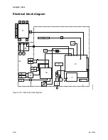
Страница 118: ...Aespire View 10 6 M1132382 Electrical block diagram Figure 10 2 Electrical block diagram AC 20 008...
Страница 137: ...10 Specifications and Theory of Operation M1132382 10 25 Figure 10 9 Gas composition related errors AB 74 027...
Страница 148: ...Aespire View I 4 M1132382...


