7 User Maintenance
M1132382
7-5
O2 cell calibration
WARNING
Do not perform O2 cell calibration while the system is
connected to a patient.
w
The O2 cell must be calibrated at the same environment
pressure at which it will be used to monitor oxygen
delivery in the patient circuit.
w
Operation at pressures other than the pressures present
during calibration may result in readings outside of the
stated monitoring accuracy.
Important
It may take a new O2 cell 90 minutes to stabilize. If the O2 cell
calibration fails after a new O2 cell has been installed, wait 90
minutes and repeat the calibration.
21% O2 cell
calibration
Complete a 21% O2 cell calibration before performing the 100% O2
cell calibration.
1. Push the Menu key.
2. Select
Setup/Calibration
.
3. Select
O2 Sensor Calibration
.
4. Select
21% O2
.
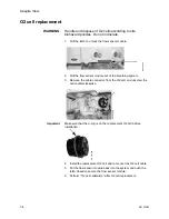
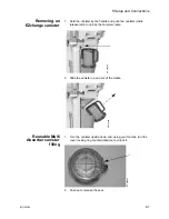
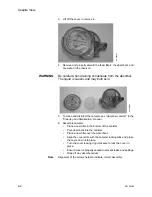
5. Remove the O2 cell from the circuit.
•
Pull the latch to unlock the flow sensor module.
•
Pull the flow sensor module out of the breathing system.
•
Remove the O2 cell by unscrewing the cell counterclockwise.
This exposes the O2 cell to room air.
6. Select
Start Calibration
. ‘Calibrating . . .’ shows on the screen
while the O2 cell is being calibrated to the room air.
7. ‘Complete’ shows on the screen upon successful calibration:
•
Reinstall the O2 cell.
•
Select
Go to Setup/Calibration Menu
.
8. If the screen shows ‘Failure,’ repeat the 21% O2 cell calibration.
9. If the calibration fails after another attempt, perform a 100% O2
cell calibration. Then try the 21% O2 cell calibration again.
10. Replace the O2 cell if repeated failures occur.
Содержание Aespire View
Страница 1: ...Aespire View User s Reference Manual Software Revision 6 X...
Страница 16: ...Aespire View 1 8 M1132382...
Страница 46: ...Aespire View 3 16 M1132382...
Страница 50: ...Aespire View 4 4 M1132382...
Страница 88: ...Aespire View 7 8 M1132382...
Страница 112: ...Aespire View 9 10 M1132382...
Страница 114: ...Aespire View 10 2 M1132382 System pneumatic circuits Figure 10 1 Pneumatic circuit diagram AC 20 001...
Страница 118: ...Aespire View 10 6 M1132382 Electrical block diagram Figure 10 2 Electrical block diagram AC 20 008...
Страница 137: ...10 Specifications and Theory of Operation M1132382 10 25 Figure 10 9 Gas composition related errors AB 74 027...
Страница 148: ...Aespire View I 4 M1132382...


