Aespire View
10-4
M1132382
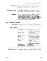
Gas supplies
Pressurized gas supplies enter the system through a pipeline or
cylinder connection. All connections have indexed fittings, filters, and
check valves. Gauges show the cylinder and pipeline pressures.
A regulator decreases the cylinder pressures to the appropriate
system pressure. A pressure relief valve helps protect the system
from high pressures.
To help prevent problems with the gas supplies:
•
Install yoke plugs on all empty cylinder connections.
•
When a pipeline supply is connected, keep the cylinder valve
closed.
•
Disconnect the pipeline supplies when the system is not in use.
WARNING
Do not leave gas cylinder valves open if the pipeline
supply is in use. Cylinder supplies could be depleted,
leaving an insufficient reserve supply in case of pipeline
failure.
O2 flow
Pipeline or regulated cylinder pressure supplies O2 directly to the
ventilator (O2 Ventilator). A secondary regulator decreases the
pressure for the flush valve and the auxiliary flowmeter.
The flush valve supplies high flows of O2 to the fresh gas outlet when
you push the flush button. The flush switch uses pressure changes to
monitor the position of the flush valve.
When the System switch is ON, O2 flows to the rest of the system
and there is a minimum flow through the O2 flowmeter.
A secondary regulator supplies a constant O2 pressure to the flow
control valve.
An electrical switch monitors the O2 supply pressure. If the pressure
is too low, an alarm appears on the ventilator.
N2O flow
A balance regulator controls the flow of N2O to the flow control valve.
Oxygen pressure at a control port adjusts the output of the regulator.
This stops flow during an O2 supply failure and ensures that the
hypoxic gas pressures decrease with the O2 supply pressure.
Changes in O2 pressure do not affect Air.
A chain linkage (Link-25) on the N2O and O2 flow controls helps keep
the O2 concentration higher than approximately 21% at the fresh gas
outlet.
Air flow
Pipeline or regulated cylinder pressure directly supply Air to the
ventilator (Air Ventilators). When the System switch is On, air flows to
the rest of the system. Because there is no balance regulator, air flow
continues at the set rate during an O2 supply failure.
Содержание Aespire View
Страница 1: ...Aespire View User s Reference Manual Software Revision 6 X...
Страница 16: ...Aespire View 1 8 M1132382...
Страница 46: ...Aespire View 3 16 M1132382...
Страница 50: ...Aespire View 4 4 M1132382...
Страница 88: ...Aespire View 7 8 M1132382...
Страница 112: ...Aespire View 9 10 M1132382...
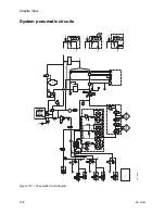
Страница 114: ...Aespire View 10 2 M1132382 System pneumatic circuits Figure 10 1 Pneumatic circuit diagram AC 20 001...
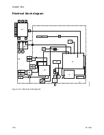
Страница 118: ...Aespire View 10 6 M1132382 Electrical block diagram Figure 10 2 Electrical block diagram AC 20 008...
Страница 137: ...10 Specifications and Theory of Operation M1132382 10 25 Figure 10 9 Gas composition related errors AB 74 027...
Страница 148: ...Aespire View I 4 M1132382...

