Aespire View
10-18
M1132382
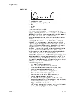
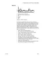
SIMV/PSV
1. Mandatory SIMV breath
2. Spontaneous pressure supported breath
3. Paw
4. Psupport
5. PEEP
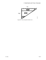
Figure 10-5 • SIMV/PSV diagram
Synchronized Intermittent Mandatory Ventilation with Pressure
Support (SIMV/PSV) is a mode in which periodic volume breaths are
delivered to the patient at preset intervals (time-triggered). Between
the machine delivered breaths, the patient can breathe
spontaneously at the rate, tidal volume, and timing that the patient
desires.
At the specified time interval, the ventilator will wait for the next
inspiratory effort from the patient. The sensitivity of this effort is
adjusted using the flow trigger level. When the ventilator senses the
beginning of inspiration it synchronously delivers a volume breath
using the set tidal volume, and inspiratory time that is set on the
ventilator. If the patient fails to make an inspiratory effort during the
trigger window time interval, the ventilator will deliver a machine
breath to the patient. The ventilator will always deliver the specific
number of breaths per minute that the clinician has set.
In SIMV/PSV, the spontaneous breaths can be pressure supported to
assist the patient in overcoming the resistance of the patient circuit
and the artificial airway. When the Psupport level is set, the ventilator
will deliver the pressure support level to the patient during inspiration.
PEEP can also be used in combination with this mode.
SIMV/PSV settings include:
•
TV - sets the amount of tidal volume.
•
RR - sets the rate of mechanically driven breaths.
•
Tinsp - sets the inspiration time for a mechanical breath.
•
Psupport - sets the pressure support level.
•
PEEP - sets the positive end expiratory pressure.
•
Pmax - sets the maximum airway pressure.
•
Rise Rate - sets the amount of time to attain Pinsp.
•
Tpause - sets the inspiratory pause time.
•
End of Breath - the drop in inspiratory flow from the peak
inspiratory flow level where the ventilator stops pressure support
mechanical inspiration and begins exhalation.
•
Trigger - sets the flow trigger level.
•
Trig Window - sets the range in percent of the exhalation phase
where a patient may trigger a mechanical breath.
AB
.9
0
.04
0
3
4
5
T
I
2
1
Содержание Aespire View
Страница 1: ...Aespire View User s Reference Manual Software Revision 6 X...
Страница 16: ...Aespire View 1 8 M1132382...
Страница 46: ...Aespire View 3 16 M1132382...
Страница 50: ...Aespire View 4 4 M1132382...
Страница 88: ...Aespire View 7 8 M1132382...
Страница 112: ...Aespire View 9 10 M1132382...
Страница 114: ...Aespire View 10 2 M1132382 System pneumatic circuits Figure 10 1 Pneumatic circuit diagram AC 20 001...
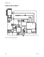
Страница 118: ...Aespire View 10 6 M1132382 Electrical block diagram Figure 10 2 Electrical block diagram AC 20 008...
Страница 137: ...10 Specifications and Theory of Operation M1132382 10 25 Figure 10 9 Gas composition related errors AB 74 027...
Страница 148: ...Aespire View I 4 M1132382...

