4-35
Cisco TelePresence System Administration Guide
OL-21845-01
Chapter 4 Troubleshooting the CTS 500
Managing CTS 500 Hardware Setup
Auxiliary LCD Displays
Each CTS 500 has five
LED
s located around the outside edges of the screen. If the user can see these
LEDs, the user is not sitting directly in front of the camera. This troubleshooting feature lets you view
and change the current state of the LEDs.
To test the LEDs:
Step 1
Log in to the Cisco TelePresence System Administration interface.
Step 2
Choose Troubleshooting > Hardware Setup.
Step 3
Click the Other Devices radio button.
Step 4
Select the LEDs tab.
Step 5
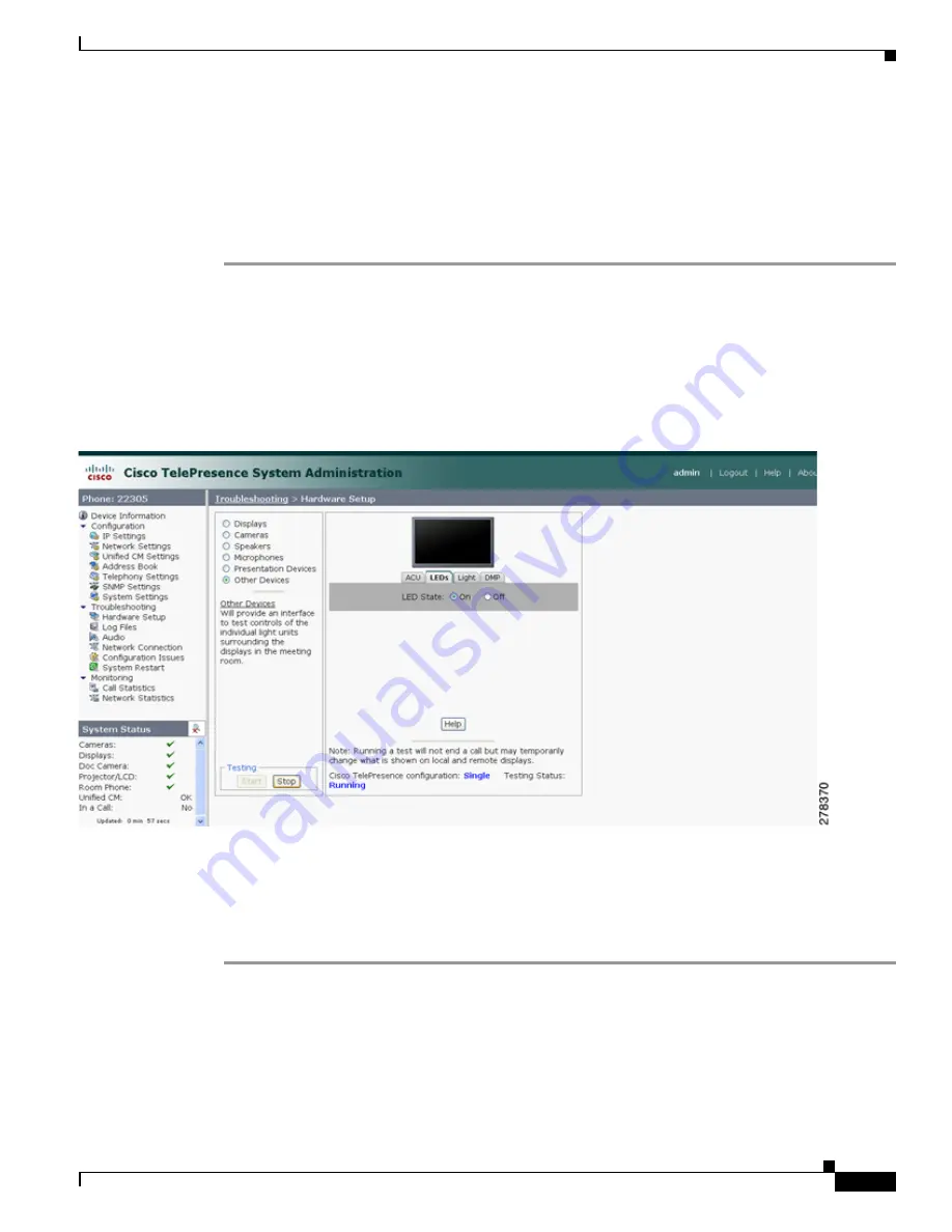
Click Start in the Testing box. The LED status is displayed, as shown in
Figure 4-18
.
Figure 4-18
CTS 500 LED Status
•
If the LED feature is enabled, the LED State On button is highlighted.
•
If the LED feature is disabled, the LED State Off button is highlighted.
Step 6
Click the LED State On or Off button to change the current state of the LEDs.
Step 7
Click Stop to end the test.
Shroud Light
Each CTS 500 has a separate shroud light. This troubleshooting feature lets you view or change the status
of the shroud light.
To test the shroud light:
Содержание CTS 1000 - TelePresence System 1000 Video Conferencing
Страница 22: ...viii Cisco TelePresence System Administration Guide OL 21845 01 What s in This Guide ...
Страница 122: ...4 50 Cisco TelePresence System Administration Guide OL 21845 01 Chapter 4 Troubleshooting the CTS 500 Where to Go Next ...
Страница 170: ...6 40 Cisco TelePresence System Administration Guide OL 21845 01 Chapter 6 Troubleshooting the CTS 1000 Where to Go Next ...
Страница 212: ...7 42 Cisco TelePresence System Administrator Guide OL 21845 01 Chapter 7 Troubleshooting the CTS 1100 Where to Go Next ...


