1-1
SECTION 1
DESCRIPTION
1.1 INTRODUCTION
WARNING
It has been determined that pressurized,
air-rich mixtures of refrigerants and air can
undergo combustion when exposed to an
ignition source.
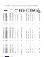
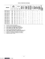
This manual contains Operating Data, Electrical
Data and Service Instructions for the refrigeration units
listed in Table 1-1. Also Table 1-1 charts some significant
differences between these models.
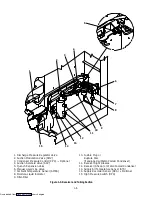
The unit, of lightweight aluminum frame
construction, is an all electric, one piece self-contained,
cooling and heating, refrigeration unit. The unit is
designed to fit in the front of a container and to serve as
the container front wall. Fork lift pockets are provided
for installation and removal of the unit.
The unit is complete with a charge of R-134a,
compressor lubricating oil (approved POE SW20
compressor oil for R-134a only), mode indicating lights,
temperature controller and is ready for operation upon
installation.
Some units are dual voltage, designed to operate on
190/230 or 380/460 volts AC, 3 phase, 50-60 hertz power.
(Refer to section 1.5) Other units are designed to operate
on 380/460 volts AC, 3 phase 50/60 hertz power only.
Operating control power is provided by a control
transformer which steps down the AC supply power
source to 18 to 24 volts and 30 to 36 voltsAC, 1 phase
control power.
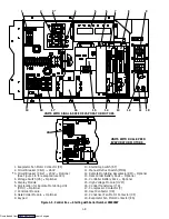
The temperature controller (Micro-Link 2) is a
microprocessor based controller. Refer to section 1.12.
Once the temperature controller is set at a desired
container
temperature,
the
unit
will operate
automatically to maintain the desired temperature
within very close limits. The control system automatically
selects cooling, holding or heating as necessary to
maintain the desired temperature within the container.
WARNING
Beware of unannounced starting of the
evaporator and condenser fans. Do not open the
condenser fan grille before turning power OFF
and disconnecting power plug.
Some units are equipped with a Carrier Transicold
DataCorder (microprocessor based recorder). Detailed
information on the DataCorder will be found in section
1.14. Some units are equipped with a Partlow mechanical
temperature recorder or a Saginomiya battery driven
temperature recorder.
Some units may have the integrated CTD EverFresh
Controlled Atmosphere option installed. Refer to the
Model Chart in Table 1-1. Separately bound manuals
covering the CTD EverFresh Controlled Atmosphere
option are also supplied, see chart below:
Manual
Number
Equipment
Covered
Type of
Manual
T-265
Controlled
Atmosphere option
Operation and
Service
T-265PL
Controlled
Atmosphere option
Service Parts
List
Some units may have a TransFRESH controlled
atmosphere system added. Contact TransFRESH
Corporation, P.O. Box 1788, Salinas, CA 93902 for
information on their system.
Downloaded from
Содержание 69NT40-489
Страница 1: ...Model 69NT40 489 T 259 Rev F Downloaded from ManualsNet com search engine ...
Страница 100: ...5 9 Figure 5 4 Electrical Wiring Diagram Model 69NT40 489 2 Sheet 2 of 2 Downloaded from ManualsNet com search engine ...
Страница 141: ...5 50 Figure 5 25 Electrical Schematic Model 69NT40 489 19 Sheet 1 of 2 Downloaded from ManualsNet com search engine ...
Страница 142: ...5 51 Figure 5 25 Electrical Schematic Model 69NT40 489 19 Sheet 2 of 2 Downloaded from ManualsNet com search engine ...
Страница 149: ...5 58 Figure 5 29 Electrical Schematic Models 69NT40 489 50 Sheet 1 of 2 Downloaded from ManualsNet com search engine ...
Страница 150: ...5 59 Figure 5 29 Electrical Schematic Models 69NT40 489 50 Sheet 2 of 2 Downloaded from ManualsNet com search engine ...
Страница 157: ...5 66 Figure 5 33 Electrical Schematic Models 69NT40 489 62 Sheet 1 of 2 Downloaded from ManualsNet com search engine ...
Страница 158: ...5 67 Figure 5 33 Electrical Schematic Models 69NT40 489 62 Sheet 2 of 2 Downloaded from ManualsNet com search engine ...
Страница 161: ...5 70 Figure 5 35 Electrical Schematic Models 69NT40 489 78 Sheet 1 of 2 Downloaded from ManualsNet com search engine ...
Страница 162: ...5 71 Figure 5 35 Electrical Schematic Models 69NT40 489 78 Sheet 2 of 2 Downloaded from ManualsNet com search engine ...
Страница 165: ...5 74 Figure 5 37 Electrical Schematic Models 69NT40 489 80 Sheet 1 of 2 Downloaded from ManualsNet com search engine ...
Страница 166: ...5 75 Figure 5 37 Electrical Schematic Models 69NT40 489 80 Sheet 2 of 2 Downloaded from ManualsNet com search engine ...
Страница 169: ...5 78 Figure 5 39 Electrical Schematic Models 69NT40 489 30 31 Sheet 1 of 2 Downloaded from ManualsNet com search engine ...
Страница 170: ...5 79 Figure 5 39 Electrical Schematic Models 69NT40 489 30 31 Sheet 2 of 2 Downloaded from ManualsNet com search engine ...

