2-6
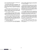
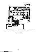
2.4.5 Economy (See Figure 2-4.)
NOTE
Setting the controller above ---10
_
C (+14
_
F)
or ---5
_
C (+23
_
F) optionally on units with
two-speed motors will place the motors in low
speed. (Contactor ES energized)
With decreasing supply air temperature and if the
supply air is above set point, the unit will be cooling with
the condenser fan motor, compressor motor and
evaporator fan motors energized. Also, at this time, the
cool light is illuminated.
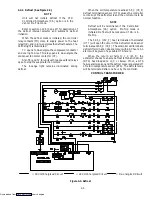
When the air temperature decreases to a tolerance
above set point, relay TI energizes and the in-range light
is illuminated. (Refer to section 1.12.5, Code 30).
If the air temperature continues to fall, modulating
cooling starts at approximately 2.5
_
C (4.5
_
F) above set
point. The modulating valve will have a variable current
up to 1.30 amps at full modulation.
During this cooling mode, a running sum of the
temperature differential (supply air temperature --- set
point) is kept. When the supply air falls below set point,
the differential is negative. The longer supply air remains
below set point, the more negative the running sum
becomes.
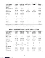
When the supply air temperature decreases to 0.2
_
C
below set point and the running sum is less than ---250
degrees C seconds, relays TN and TC de-energize
shutting off the condenser fan and compressor motors.
Also, the cool light is de-energized.
The evaporator fan motors continue to run to
circulate air throughout the container. The in-range light
remains illuminated as long as the supply air is within a
tolerance of set point, and the 15 minute out of range
time has not elapsed.
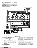
= 18 Volt Energized Circuit
= 24 Volt Energized Circuit
= De-energized Circuit
Figure 2-4. Economy Mode
CONTROL TRANSFORMER
Downloaded from
Содержание 69NT40-489
Страница 1: ...Model 69NT40 489 T 259 Rev F Downloaded from ManualsNet com search engine ...
Страница 100: ...5 9 Figure 5 4 Electrical Wiring Diagram Model 69NT40 489 2 Sheet 2 of 2 Downloaded from ManualsNet com search engine ...
Страница 141: ...5 50 Figure 5 25 Electrical Schematic Model 69NT40 489 19 Sheet 1 of 2 Downloaded from ManualsNet com search engine ...
Страница 142: ...5 51 Figure 5 25 Electrical Schematic Model 69NT40 489 19 Sheet 2 of 2 Downloaded from ManualsNet com search engine ...
Страница 149: ...5 58 Figure 5 29 Electrical Schematic Models 69NT40 489 50 Sheet 1 of 2 Downloaded from ManualsNet com search engine ...
Страница 150: ...5 59 Figure 5 29 Electrical Schematic Models 69NT40 489 50 Sheet 2 of 2 Downloaded from ManualsNet com search engine ...
Страница 157: ...5 66 Figure 5 33 Electrical Schematic Models 69NT40 489 62 Sheet 1 of 2 Downloaded from ManualsNet com search engine ...
Страница 158: ...5 67 Figure 5 33 Electrical Schematic Models 69NT40 489 62 Sheet 2 of 2 Downloaded from ManualsNet com search engine ...
Страница 161: ...5 70 Figure 5 35 Electrical Schematic Models 69NT40 489 78 Sheet 1 of 2 Downloaded from ManualsNet com search engine ...
Страница 162: ...5 71 Figure 5 35 Electrical Schematic Models 69NT40 489 78 Sheet 2 of 2 Downloaded from ManualsNet com search engine ...
Страница 165: ...5 74 Figure 5 37 Electrical Schematic Models 69NT40 489 80 Sheet 1 of 2 Downloaded from ManualsNet com search engine ...
Страница 166: ...5 75 Figure 5 37 Electrical Schematic Models 69NT40 489 80 Sheet 2 of 2 Downloaded from ManualsNet com search engine ...
Страница 169: ...5 78 Figure 5 39 Electrical Schematic Models 69NT40 489 30 31 Sheet 1 of 2 Downloaded from ManualsNet com search engine ...
Страница 170: ...5 79 Figure 5 39 Electrical Schematic Models 69NT40 489 30 31 Sheet 2 of 2 Downloaded from ManualsNet com search engine ...


