2-5
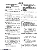
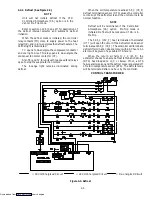
2.4.4 Defrost (See Figure 2-3.)
NOTE
Unit will not initiate defrost if the CTD
Controlled Atmosphere (CA) option is in the
Vent or Pre-Trip mode.
Refer to section 1.12.5 (Code 27) for description of
the defrost interval selector and automatic defrost
initiation.
When the defrost mode is initiated, the controller
relay contacts (TH) close to supply power to the heat
relay (HR) and in turn, energizes the defrost heaters. The
defrost light is illuminated.
TC opens to de-energize the compressor contactor
and cool light. Also TN relay opens to de-energize the
condenser fan motor contactor (CF).
Also TE (and TV for units with two speed fans) relays
open to stop the evaporator fan motors.
The in-range light remains illuminated during
defrost.
When the coil temperature reaches 25.6
_
C (78
_
F)
defrost termination sensor (DTS) causes the controller
to interrupt the defrost cycle and the unit returns to its
normal function.
NOTE
Defrost will be terminated if the Controlled
Atmosphere (CA) option Pre-Trip mode is
initiated. Defrost will be locked-out if CA is in
Pre-Trip.
The 54.5
_
C (130
_
F) heat termination thermostat
(HTT) will open the circuit if the defrost mode does not
terminate at 25.6
_
C (78
_
F). The controller will terminate
defrost if termination does not occur within 2.0 hours. An
alarm will be given of a possible DTS failure.
When the return air falls to 7
_
C (45
_
F), the
controller checks to ensure defrost termination sensor
(DTS) has dropped to 10
_
C or below. If not, a DTS
failure alarm is given and the defrost mode is operated off
of return temperature sensor (RTS). The defrost mode
will be terminated after one hour by the controller.
CONTROL TRANSFORMER
= 18 Volt Energized Circuit
= 24 Volt Energized Circuit
= De-energized Circuit
Figure 2-3. Defrost
Downloaded from
Содержание 69NT40-489
Страница 1: ...Model 69NT40 489 T 259 Rev F Downloaded from ManualsNet com search engine ...
Страница 100: ...5 9 Figure 5 4 Electrical Wiring Diagram Model 69NT40 489 2 Sheet 2 of 2 Downloaded from ManualsNet com search engine ...
Страница 141: ...5 50 Figure 5 25 Electrical Schematic Model 69NT40 489 19 Sheet 1 of 2 Downloaded from ManualsNet com search engine ...
Страница 142: ...5 51 Figure 5 25 Electrical Schematic Model 69NT40 489 19 Sheet 2 of 2 Downloaded from ManualsNet com search engine ...
Страница 149: ...5 58 Figure 5 29 Electrical Schematic Models 69NT40 489 50 Sheet 1 of 2 Downloaded from ManualsNet com search engine ...
Страница 150: ...5 59 Figure 5 29 Electrical Schematic Models 69NT40 489 50 Sheet 2 of 2 Downloaded from ManualsNet com search engine ...
Страница 157: ...5 66 Figure 5 33 Electrical Schematic Models 69NT40 489 62 Sheet 1 of 2 Downloaded from ManualsNet com search engine ...
Страница 158: ...5 67 Figure 5 33 Electrical Schematic Models 69NT40 489 62 Sheet 2 of 2 Downloaded from ManualsNet com search engine ...
Страница 161: ...5 70 Figure 5 35 Electrical Schematic Models 69NT40 489 78 Sheet 1 of 2 Downloaded from ManualsNet com search engine ...
Страница 162: ...5 71 Figure 5 35 Electrical Schematic Models 69NT40 489 78 Sheet 2 of 2 Downloaded from ManualsNet com search engine ...
Страница 165: ...5 74 Figure 5 37 Electrical Schematic Models 69NT40 489 80 Sheet 1 of 2 Downloaded from ManualsNet com search engine ...
Страница 166: ...5 75 Figure 5 37 Electrical Schematic Models 69NT40 489 80 Sheet 2 of 2 Downloaded from ManualsNet com search engine ...
Страница 169: ...5 78 Figure 5 39 Electrical Schematic Models 69NT40 489 30 31 Sheet 1 of 2 Downloaded from ManualsNet com search engine ...
Страница 170: ...5 79 Figure 5 39 Electrical Schematic Models 69NT40 489 30 31 Sheet 2 of 2 Downloaded from ManualsNet com search engine ...

