ii
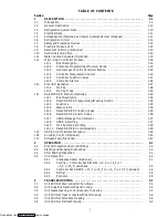
TABLE OF CONTENTS (CONTINUED)
Section
Page
3.7
Abnormal Pressures (Cooling)
3-3
. . . . . . . . . . . . . . . . . . . . . . . . . . . . . . . . . . . . . . . . . . . .
3.8
Abnormal Noise or Vibrations
3-3
. . . . . . . . . . . . . . . . . . . . . . . . . . . . . . . . . . . . . . . . . . . .
3.9
Temperature Controller Malfunction
3-3
. . . . . . . . . . . . . . . . . . . . . . . . . . . . . . . . . . . . . .
3.10
No Evaporator Air Flow or Restricted Air Flow
3-3
. . . . . . . . . . . . . . . . . . . . . . . . . . . . .
3.11
Thermostatic Expansion Valve Malfunction
3-4
. . . . . . . . . . . . . . . . . . . . . . . . . . . . . . . . .
3.12
Power Autotransformer Malfunction
3-4
. . . . . . . . . . . . . . . . . . . . . . . . . . . . . . . . . . . . . .
3.13
Evaporator Motor Transformer Malfunction
3-4
. . . . . . . . . . . . . . . . . . . . . . . . . . . . . . . .
3.14
Water-Cooled Condenser or Water Pressure Switch Malfunction
3-4
. . . . . . . . . . . . . . .
4
SERVICE
4-1
. . . . . . . . . . . . . . . . . . . . . . . . . . . . . . . . . . . . . . . . . . . . . . . . . . . . . . . . . . . . .
4.1
Manifold Gauge Set
4-1
. . . . . . . . . . . . . . . . . . . . . . . . . . . . . . . . . . . . . . . . . . . . . . . . . . . .
4.2
Suction and Discharge Service Valves
4-3
. . . . . . . . . . . . . . . . . . . . . . . . . . . . . . . . . . . . . .
4.3
Pumping the Unit Down
4-3
. . . . . . . . . . . . . . . . . . . . . . . . . . . . . . . . . . . . . . . . . . . . . . . . .
4.4
Refrigerant Leak Checking
4-3
. . . . . . . . . . . . . . . . . . . . . . . . . . . . . . . . . . . . . . . . . . . . . .
4.5
Evacuation and Dehydration
4-3
. . . . . . . . . . . . . . . . . . . . . . . . . . . . . . . . . . . . . . . . . . . . .
4.5.1
General
4-3
. . . . . . . . . . . . . . . . . . . . . . . . . . . . . . . . . . . . . . . . . . . . . . . . . . . . . .
4.5.2
Preparation
4-3
. . . . . . . . . . . . . . . . . . . . . . . . . . . . . . . . . . . . . . . . . . . . . . . . . . .
4.5.3
Procedure
4-4
. . . . . . . . . . . . . . . . . . . . . . . . . . . . . . . . . . . . . . . . . . . . . . . . . . . .
4.6
Refrigerant Charge
4-4
. . . . . . . . . . . . . . . . . . . . . . . . . . . . . . . . . . . . . . . . . . . . . . . . . . . . .
4.6.1
Checking the Refrigerant Charge
4-4
. . . . . . . . . . . . . . . . . . . . . . . . . . . . . . . . .
4.6.2
Adding Refrigerant to System (Full Charge)
4-4
. . . . . . . . . . . . . . . . . . . . . . . .
4.6.3
Adding Refrigerant to System (Partial Charge)
4-4
. . . . . . . . . . . . . . . . . . . . .
4.7
Compressor --- Model 06DR
4-6
. . . . . . . . . . . . . . . . . . . . . . . . . . . . . . . . . . . . . . . . . . . . .
4.8
Compressor Disassembly
4-7
. . . . . . . . . . . . . . . . . . . . . . . . . . . . . . . . . . . . . . . . . . . . . . . .
4.9
Compressor Reassembly
4-9
. . . . . . . . . . . . . . . . . . . . . . . . . . . . . . . . . . . . . . . . . . . . . . . . .
4.10
Compressor Oil Level
4-10
. . . . . . . . . . . . . . . . . . . . . . . . . . . . . . . . . . . . . . . . . . . . . . . . . . .
4.11
Moisture-Liquid Indicator
4-11
. . . . . . . . . . . . . . . . . . . . . . . . . . . . . . . . . . . . . . . . . . . . . . .
4.12
Filter-Drier
4-11
. . . . . . . . . . . . . . . . . . . . . . . . . . . . . . . . . . . . . . . . . . . . . . . . . . . . . . . . . . . .
4.13
High Pressure Switch
4-11
. . . . . . . . . . . . . . . . . . . . . . . . . . . . . . . . . . . . . . . . . . . . . . . . . . . .
4.13.1
Replacing High Pressure Switch
4-11
. . . . . . . . . . . . . . . . . . . . . . . . . . . . . . . . . .
4.13.2
Checking High Pressure Switch
4-12
. . . . . . . . . . . . . . . . . . . . . . . . . . . . . . . . . . .
4.14
Evaporator Coil and Heater Assembly
4-12
. . . . . . . . . . . . . . . . . . . . . . . . . . . . . . . . . . . . .
4.15
Evaporator Fan and Motor Assembly
4-12
. . . . . . . . . . . . . . . . . . . . . . . . . . . . . . . . . . . . . .
4.16
Evaporator Coil Heaters
4-13
. . . . . . . . . . . . . . . . . . . . . . . . . . . . . . . . . . . . . . . . . . . . . . . . .
4.17
Condenser Coil
4-13
. . . . . . . . . . . . . . . . . . . . . . . . . . . . . . . . . . . . . . . . . . . . . . . . . . . . . . . .
4.18
Condenser Fan and Motor Assembly
4-13
. . . . . . . . . . . . . . . . . . . . . . . . . . . . . . . . . . . . . .
4.19
Recording Thermometer (Partlow)
4-13
. . . . . . . . . . . . . . . . . . . . . . . . . . . . . . . . . . . . . . . .
4.20
Recording Thermometer (Saginomiya)
4-15
. . . . . . . . . . . . . . . . . . . . . . . . . . . . . . . . . . . . .
4.21
Maintenance of Painted Surfaces
4-15
. . . . . . . . . . . . . . . . . . . . . . . . . . . . . . . . . . . . . . . . .
4.22
Power Autotransformer (Optional)
4-16
. . . . . . . . . . . . . . . . . . . . . . . . . . . . . . . . . . . . . . . .
4.23
Sensor Checkout Procedure (AMBS, DTS, RRS, RTS, SRS & STS)
4-16
. . . . . . . . . . . .
4.23.1
Checking Sensor (RRS, RTS, SRS or STS)
4-16
. . . . . . . . . . . . . . . . . . . . . . . . .
4.23.2
Replacing Sensor (RRS, RTS, SRS or STS)
4-16
. . . . . . . . . . . . . . . . . . . . . . . .
4.23.3
Checking Sensor (AMBS or DTS)
4-17
. . . . . . . . . . . . . . . . . . . . . . . . . . . . . . . .
4.23.4
Replacing Sensor (AMBS or DTS)
4-17
. . . . . . . . . . . . . . . . . . . . . . . . . . . . . . . .
4.24
Suction Solenoid Valve
4-17
. . . . . . . . . . . . . . . . . . . . . . . . . . . . . . . . . . . . . . . . . . . . . . . . . .
4.25
Suction Modulation Valve
4-18
. . . . . . . . . . . . . . . . . . . . . . . . . . . . . . . . . . . . . . . . . . . . . . .
4.26
Thermostatic Expansion Valve
4-19
. . . . . . . . . . . . . . . . . . . . . . . . . . . . . . . . . . . . . . . . . . . .
4.27
Evaporator Fan Motor Capacitors (Optional)
4-20
. . . . . . . . . . . . . . . . . . . . . . . . . . . . . . .
4.28
Controller and DataCORDER
4-21
. . . . . . . . . . . . . . . . . . . . . . . . . . . . . . . . . . . . . . . . . . .
4.28.1
Controller Programming Procedure
4-22
. . . . . . . . . . . . . . . . . . . . . . . . . . . . . . .
4.28.2
DataCORDER Programming Procedure
4-23
. . . . . . . . . . . . . . . . . . . . . . . . . .
4.28.3
Controller Trouble-Shooting
4-23
. . . . . . . . . . . . . . . . . . . . . . . . . . . . . . . . . . . . .
4.29
Water-Cooled Condenser
4-24
. . . . . . . . . . . . . . . . . . . . . . . . . . . . . . . . . . . . . . . . . . . . . . . .
5
ELECTRICAL WIRING SCHEMATIC AND DIAGRAMS
5-1
. . . . . . . . . . . . . . . . . . . .
5.1
Introduction
5-1
. . . . . . . . . . . . . . . . . . . . . . . . . . . . . . . . . . . . . . . . . . . . . . . . . . . . . . . . . . .
Downloaded from
Содержание 69NT40-489
Страница 1: ...Model 69NT40 489 T 259 Rev F Downloaded from ManualsNet com search engine ...
Страница 100: ...5 9 Figure 5 4 Electrical Wiring Diagram Model 69NT40 489 2 Sheet 2 of 2 Downloaded from ManualsNet com search engine ...
Страница 141: ...5 50 Figure 5 25 Electrical Schematic Model 69NT40 489 19 Sheet 1 of 2 Downloaded from ManualsNet com search engine ...
Страница 142: ...5 51 Figure 5 25 Electrical Schematic Model 69NT40 489 19 Sheet 2 of 2 Downloaded from ManualsNet com search engine ...
Страница 149: ...5 58 Figure 5 29 Electrical Schematic Models 69NT40 489 50 Sheet 1 of 2 Downloaded from ManualsNet com search engine ...
Страница 150: ...5 59 Figure 5 29 Electrical Schematic Models 69NT40 489 50 Sheet 2 of 2 Downloaded from ManualsNet com search engine ...
Страница 157: ...5 66 Figure 5 33 Electrical Schematic Models 69NT40 489 62 Sheet 1 of 2 Downloaded from ManualsNet com search engine ...
Страница 158: ...5 67 Figure 5 33 Electrical Schematic Models 69NT40 489 62 Sheet 2 of 2 Downloaded from ManualsNet com search engine ...
Страница 161: ...5 70 Figure 5 35 Electrical Schematic Models 69NT40 489 78 Sheet 1 of 2 Downloaded from ManualsNet com search engine ...
Страница 162: ...5 71 Figure 5 35 Electrical Schematic Models 69NT40 489 78 Sheet 2 of 2 Downloaded from ManualsNet com search engine ...
Страница 165: ...5 74 Figure 5 37 Electrical Schematic Models 69NT40 489 80 Sheet 1 of 2 Downloaded from ManualsNet com search engine ...
Страница 166: ...5 75 Figure 5 37 Electrical Schematic Models 69NT40 489 80 Sheet 2 of 2 Downloaded from ManualsNet com search engine ...
Страница 169: ...5 78 Figure 5 39 Electrical Schematic Models 69NT40 489 30 31 Sheet 1 of 2 Downloaded from ManualsNet com search engine ...
Страница 170: ...5 79 Figure 5 39 Electrical Schematic Models 69NT40 489 30 31 Sheet 2 of 2 Downloaded from ManualsNet com search engine ...

