1-17
Configuration Software:
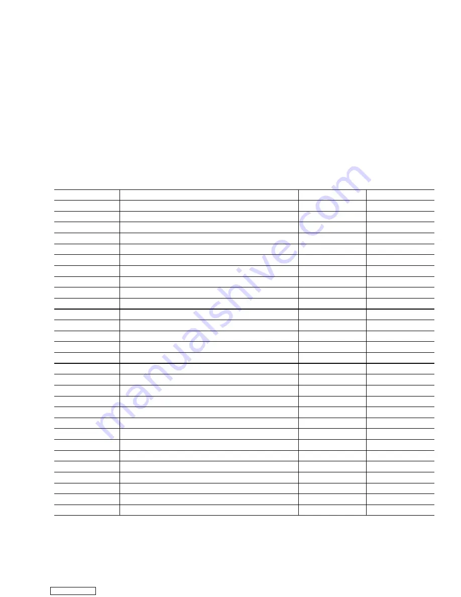
This is the software that tells the Operational Soft-
ware what physical components are built into the con-
tainer unit. Refer to Table 1-4.
Programming cards with either Operational Soft-
ware or Configuration Software are available thru CTD
Replacement Components Group.
The use of a programming card in the field, should
only occur under unusual circumstances. Some of these
circumstances may include:
a. A Controller module has an older version of Opera-
tional Software, and the need exists to upgrade to a newer
version of the software.
b. A physical component in the container unit is
changed to something different, resulting in a different
configuration for the unit.
c. A Controller module was damaged in such a way that
the integrity or existence of software within the module,
is questionable.
Procedure for loading software:
Refer to section 4.28.1.
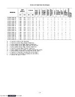
Table 1-4. Configuration Variables
Configuration #
TITLE
Default
Option
1
Bypass Valve Enable
In
Out
2
Evaporator Fan Speed
SS (Single)
dS (Dual)
3
Tri Sensor
dUAL
tHrEE
4
Dehumidification Mode
On
Off
5
Probe Calibration
noCal
CAL
6
Condenser Fan Speed Select
Off (Single)
On (Variable)
7
Unit Selection, 20FT/ 40FT/45FT
40ft
20ft,45
8
Single Phase/Three Phase Motor
1Ph
3Ph
9
Refrigerant Selection
r22
r12,r134a,bLEnd
10
Advanced Pre---Trip
P (Advanced)
none
11
Defrost “Off” Selection
noOFF
OFF
12
TXV/Solenoid Quench Valve
In (Solenoid)
Out (TXV)
13
Unloader
In
Out
14
Condenser Pressure Control
Out
In
15
Discharge Temperature Sensor
In
Out
16
Trim Heat
In
Out
17
RMU Command Set
nEW (Core)
Old (Phase 2)
18
Heater
Old (Low Watt)
nEW (High Watt)
19
Controlled Atmosphere
Out
In
20
Pressure Sensors (Transducers)
Out
In
21
Auto-Transformer
Out
In
22
Economy Mode Option
Off
On
23
Defrost Interval Timer Save Option
noSAV
SAV
24
Advanced Pre-Trip Enhanced Test
Off
On
25
Pre-Trip Test Points/Results Recording
rSLts
data
26
Heat Lockout
Set to ---10
_
C
Set to---5
_
C
27
Suction Temperature Display
Out
In
28
Bulb Mode
Nor
bulb
29
Arctic Mode
Out
In
Downloaded from
Содержание 69NT40-489
Страница 1: ...Model 69NT40 489 T 259 Rev F Downloaded from ManualsNet com search engine ...
Страница 100: ...5 9 Figure 5 4 Electrical Wiring Diagram Model 69NT40 489 2 Sheet 2 of 2 Downloaded from ManualsNet com search engine ...
Страница 141: ...5 50 Figure 5 25 Electrical Schematic Model 69NT40 489 19 Sheet 1 of 2 Downloaded from ManualsNet com search engine ...
Страница 142: ...5 51 Figure 5 25 Electrical Schematic Model 69NT40 489 19 Sheet 2 of 2 Downloaded from ManualsNet com search engine ...
Страница 149: ...5 58 Figure 5 29 Electrical Schematic Models 69NT40 489 50 Sheet 1 of 2 Downloaded from ManualsNet com search engine ...
Страница 150: ...5 59 Figure 5 29 Electrical Schematic Models 69NT40 489 50 Sheet 2 of 2 Downloaded from ManualsNet com search engine ...
Страница 157: ...5 66 Figure 5 33 Electrical Schematic Models 69NT40 489 62 Sheet 1 of 2 Downloaded from ManualsNet com search engine ...
Страница 158: ...5 67 Figure 5 33 Electrical Schematic Models 69NT40 489 62 Sheet 2 of 2 Downloaded from ManualsNet com search engine ...
Страница 161: ...5 70 Figure 5 35 Electrical Schematic Models 69NT40 489 78 Sheet 1 of 2 Downloaded from ManualsNet com search engine ...
Страница 162: ...5 71 Figure 5 35 Electrical Schematic Models 69NT40 489 78 Sheet 2 of 2 Downloaded from ManualsNet com search engine ...
Страница 165: ...5 74 Figure 5 37 Electrical Schematic Models 69NT40 489 80 Sheet 1 of 2 Downloaded from ManualsNet com search engine ...
Страница 166: ...5 75 Figure 5 37 Electrical Schematic Models 69NT40 489 80 Sheet 2 of 2 Downloaded from ManualsNet com search engine ...
Страница 169: ...5 78 Figure 5 39 Electrical Schematic Models 69NT40 489 30 31 Sheet 1 of 2 Downloaded from ManualsNet com search engine ...
Страница 170: ...5 79 Figure 5 39 Electrical Schematic Models 69NT40 489 30 31 Sheet 2 of 2 Downloaded from ManualsNet com search engine ...

