1-39
1.14.10
DataCorder Communications
a. DataCorder Retrieval --- Interrogation
Data retrieval from the DataCorder can be
accomplished with two devices: (1) a stand-alone DOS
based portable computer with appropriate cable and
software or (2) a Remote Monitoring Unit (RMU).
NOTE
The RMU designation is used in the industry,
however, be aware that CTD uses the
designation CI (Communications Interface
Module) on its schematics.
The optional interrogation software for a portable
computer is supplied on a 3.5 and 5.25 inch floppy disk.
This software allows interrogation, screen view of the
data, hard copy report generation, cold treatment probe
calibration, cold treatment initialization and file
management.
NOTE
Refer to the Interrogation manual 62-02575 for
a more detailed explanation of the interrogation
software.
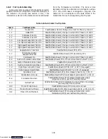
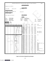
A short report on specific interrogations can be
displayed on the computer to identify key information
such as Trip Start, Power Outages, and Temperature
Out-of-Range conditions.
1.15 USDA COLD TREATMENT PROCEDURE
Sustained cold temperature has been employed as an
effective postharvest method for the control of the
Mediterranean and certain other tropical fruit flies.
Exposing infested fruit to temperatures of 2.2 degrees
Celsius (36
_
F) or below for specific periods results in the
mortality of the various stages of this group of notoriously
injurious insects.
In response to the demand to replace fumigation
with this environmentally sound process, Carrier has
integrated this Cold Treatment capability into its
DataCorder. These units have the ability to maintain the
container temperature within 1/4 degree Celsius of
setpoint and record minute changes in product
temperature within the DataCorder memory and thus
meet USDA criteria (refer to section 1.14.8).
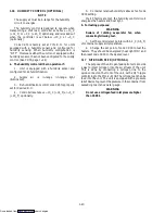
The following is a summary of the steps required to
initiate a USDA Cold Treatment.
a. Pre-cool the container to the treatment
temperature or below.
b. The product should be pre-cooled to treatment
temperature.
c. Install the DataCorder module battery pack.
d. Probe calibration is achieved by ice bathing the
three USDA probes and performing the calibration
function on a DOS based portable computer. This
calibration determines the three probe offsets. Refer to
the Interrogation manual 62-02575 for more details.
e. The product is then loaded directly from the
pre-cooling storage area to the container so that the
product temperature does not rise.
f. Placement of probes --- there are three probes
required for a USDA cold treatment procedure.
Sensor 1
Place in pulp of the product located next
to the return air intake.
Sensor 2
Place in pulp of the product five feet
from the end of the load for 40 ft. con-
tainers and three feet from the end of
the load for 20 ft. containers. This probe
should be placed in a center carton at
1/2 the height of the load.
Sensor 3
Place in pulp of product five feet from
the end of the load for 40 ft. containers
and three feet from the end of the load
for 20 ft. containers. This probe should
be placed in a carton at a side wall at 1/2
the height of the load.
g. To initiate USDA Recording (begin the cold
treatment recording) connect the Interrogator and
perform the configuration as follows:
1. Trip Start
2. Trip Comment
3
Configure for 5 probes
4. 1 hour logging interval
5. USDA temperature log in
6. Two byte memory storage format
7. Probe calibration
h. Interrogation software is available for DOS
based personal computers which allow retrieval of trip
data from the DataCorder memory. Contact a Carrier
Transicold Service Parts representative for details.
Downloaded from
Содержание 69NT40-489
Страница 1: ...Model 69NT40 489 T 259 Rev F Downloaded from ManualsNet com search engine ...
Страница 100: ...5 9 Figure 5 4 Electrical Wiring Diagram Model 69NT40 489 2 Sheet 2 of 2 Downloaded from ManualsNet com search engine ...
Страница 141: ...5 50 Figure 5 25 Electrical Schematic Model 69NT40 489 19 Sheet 1 of 2 Downloaded from ManualsNet com search engine ...
Страница 142: ...5 51 Figure 5 25 Electrical Schematic Model 69NT40 489 19 Sheet 2 of 2 Downloaded from ManualsNet com search engine ...
Страница 149: ...5 58 Figure 5 29 Electrical Schematic Models 69NT40 489 50 Sheet 1 of 2 Downloaded from ManualsNet com search engine ...
Страница 150: ...5 59 Figure 5 29 Electrical Schematic Models 69NT40 489 50 Sheet 2 of 2 Downloaded from ManualsNet com search engine ...
Страница 157: ...5 66 Figure 5 33 Electrical Schematic Models 69NT40 489 62 Sheet 1 of 2 Downloaded from ManualsNet com search engine ...
Страница 158: ...5 67 Figure 5 33 Electrical Schematic Models 69NT40 489 62 Sheet 2 of 2 Downloaded from ManualsNet com search engine ...
Страница 161: ...5 70 Figure 5 35 Electrical Schematic Models 69NT40 489 78 Sheet 1 of 2 Downloaded from ManualsNet com search engine ...
Страница 162: ...5 71 Figure 5 35 Electrical Schematic Models 69NT40 489 78 Sheet 2 of 2 Downloaded from ManualsNet com search engine ...
Страница 165: ...5 74 Figure 5 37 Electrical Schematic Models 69NT40 489 80 Sheet 1 of 2 Downloaded from ManualsNet com search engine ...
Страница 166: ...5 75 Figure 5 37 Electrical Schematic Models 69NT40 489 80 Sheet 2 of 2 Downloaded from ManualsNet com search engine ...
Страница 169: ...5 78 Figure 5 39 Electrical Schematic Models 69NT40 489 30 31 Sheet 1 of 2 Downloaded from ManualsNet com search engine ...
Страница 170: ...5 79 Figure 5 39 Electrical Schematic Models 69NT40 489 30 31 Sheet 2 of 2 Downloaded from ManualsNet com search engine ...


