1-10
1.2 GENERAL DESCRIPTION
a. Compressor Section
NOTE
Check the compressor Serial/Model Number
plate for CFM displacement, refer to Table 1-2.
The compressor section includes the compressor
(with high pressure switch), optional crankcase heater,
power cable storage compartment, and an optional
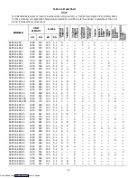
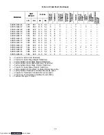
transformer (Refer to Table 1-1 and Figure 1-6) which is
located to the left of the compressor.
NOTE
The dual voltage evaporator transformer is
always on line and supplies 460v to the
evaporator motor contactor, and 230v to the
control transformer.
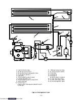
This section also contains the suction modulation
valve, suction solenoid valve, quench expansion valve,
moisture-liquid indicator, manual liquid line valve,
filter-drier, fusible plug or rupture disc, discharge
pressure regulator valve and optional discharge/suction
pressure transducers.
The supply air temperature sensor (STS), supply
recorder sensor (SRS) and ambient sensor (AMBS) are
located at the right side of the compressor.
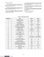
Table 1-2. Compressor Model Number
Significance Chart
06DR2419CC1970
1st, 2nd & 3rd DIGIT
06D Hermetic Reciprocal
4th DIGIT
R
Refrigeration Duty
6th & 7th DIGIT
DISPLACEMENT
41
41CFM
b. Condenser Section
The condensing section consists of a condenser fan
motor, condenser fan and an air-cooled condenser coil.
When the unit is operating, air is pulled in the bottom of
the coil and discharges horizontally out through the front
of the condenser fan grille.
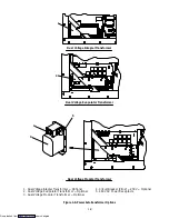
c. Evaporator Section
The evaporator section contains the optional
mechanical temperature recording bulb, return recorder
sensor (RRS), return temperature sensor (RTS),
thermostatic expansion valve, evaporator fan motors and
fans (2), evaporator coil and heaters, drain pan and
heater, defrost termination sensor, heat termination
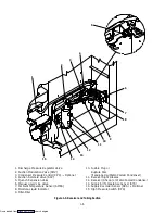
switch, and a heat exchanger. See Figure 1-2 and
Figure 1-3 for sensor location.
The evaporator fans circulate air throughout the
container by pulling air in the top of the refrigeration unit
and directing the air through the evaporator coil where it
is either heated or cooled, and then discharged out the
bottom of the refrigeration unit into the container.
Some units are equipped with two-speed evaporator
fan motors. Refer to Table 1-1. When transporting
perishable (chilled) commodities, the fan motors will
normally be in high speed above ---10
_
C (+14
_
F) or
---5
_
C (+23
_
F) optionally. If the unit is equipped with
economy mode and it is turned on, the fan motors will run
in low speed.
The evaporator coil heaters are accessible by
removing the front, lower access panel. The defrost
termination sensor (DTS) is located on the coil center
tube-sheet and may be serviced by removing the upper
rear, panel or by removing the left front, upper access
panel and reaching through the evaporator fan venturi
AFTER POWER IS TURNED OFF AND POWER
PLUG DISCONNECTED.
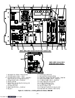
d. Control Box
The control box includes the manual switches, circuit
breaker(s), contactors, transformers, fuses, keypad,
display module, high voltage module, controller module
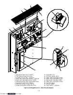
and an optional DataCorder module. (See Figure 1-4 or
Figure 1-5).
1.3 REFRIGERATION SYSTEM DATA
a. Compressor --- Motor Assembly
No. of Cylinders:
6
Model:
06DR
Weight (Dry):
260 lb (118 kg)
b. Approved Compressor Oil
Castrol Icematic --- SW20
c. Compressor Oil Charge
3.6 liters (7.6 U.S. pints)
d. Compressor Oil Sight Glass
The oil level range should be between the bottom to
1/8 of the sight glass, with the compressor off.
e. Expansion Valve Superheat
Verify at ---18
_
C (0
_
F) container box temperature:
3.36 to 4.48
_
C (6 to 8
_
F)
f. Heater Termination Thermostat
Opens:
54 (
¦
3)
_
C = 130 (
¦
5)
_
F
Closes:
38 (
¦
4)
_
C = 100 (
¦
7)
_
F
g. High Pressure Switch
Cutout:
25 (
¦
0.7) kg/cm
@
= 350 (
¦
10) psig
Cut-In:
18 (
¦
0.7) kg/cm
@
= 250 (
¦
10) psig
h. Refrigeration Charge
Refer to Table 1-1.
i. Fusible Plug
Melting point:
93
_
C = (200
_
F)
j. Rupture Disc (Used on water-cooled units only)
Bursts at:
35 ±5% kg/cm
@
= (500 ±5% psig)
k. Unit Weight
Refer to Table 1-1.
Downloaded from
Содержание 69NT40-489
Страница 1: ...Model 69NT40 489 T 259 Rev F Downloaded from ManualsNet com search engine ...
Страница 100: ...5 9 Figure 5 4 Electrical Wiring Diagram Model 69NT40 489 2 Sheet 2 of 2 Downloaded from ManualsNet com search engine ...
Страница 141: ...5 50 Figure 5 25 Electrical Schematic Model 69NT40 489 19 Sheet 1 of 2 Downloaded from ManualsNet com search engine ...
Страница 142: ...5 51 Figure 5 25 Electrical Schematic Model 69NT40 489 19 Sheet 2 of 2 Downloaded from ManualsNet com search engine ...
Страница 149: ...5 58 Figure 5 29 Electrical Schematic Models 69NT40 489 50 Sheet 1 of 2 Downloaded from ManualsNet com search engine ...
Страница 150: ...5 59 Figure 5 29 Electrical Schematic Models 69NT40 489 50 Sheet 2 of 2 Downloaded from ManualsNet com search engine ...
Страница 157: ...5 66 Figure 5 33 Electrical Schematic Models 69NT40 489 62 Sheet 1 of 2 Downloaded from ManualsNet com search engine ...
Страница 158: ...5 67 Figure 5 33 Electrical Schematic Models 69NT40 489 62 Sheet 2 of 2 Downloaded from ManualsNet com search engine ...
Страница 161: ...5 70 Figure 5 35 Electrical Schematic Models 69NT40 489 78 Sheet 1 of 2 Downloaded from ManualsNet com search engine ...
Страница 162: ...5 71 Figure 5 35 Electrical Schematic Models 69NT40 489 78 Sheet 2 of 2 Downloaded from ManualsNet com search engine ...
Страница 165: ...5 74 Figure 5 37 Electrical Schematic Models 69NT40 489 80 Sheet 1 of 2 Downloaded from ManualsNet com search engine ...
Страница 166: ...5 75 Figure 5 37 Electrical Schematic Models 69NT40 489 80 Sheet 2 of 2 Downloaded from ManualsNet com search engine ...
Страница 169: ...5 78 Figure 5 39 Electrical Schematic Models 69NT40 489 30 31 Sheet 1 of 2 Downloaded from ManualsNet com search engine ...
Страница 170: ...5 79 Figure 5 39 Electrical Schematic Models 69NT40 489 30 31 Sheet 2 of 2 Downloaded from ManualsNet com search engine ...

