1-32
1.14 DATACORDER MODULE (OPTIONAL)
1. DataCorder Module
2. Battery Pack (Optional)
3. Software Port
4. Connector
5. Status LED’s
6. Fuse
7. Manual Battery Switch
1
2
3
4
5
6
7
4
4
Figure 1-11. DataCorder Module
1.14.1 Brief Description
WARNING
Do not attempt to service the DataCorder
module, breaking the warranty seal will void the
warranty.
CAUTION
Remove DataCorder module and unplug all wire
harness connectors before performing any arc
welding on any part of the container.
Do not remove wire harnesses from module
unless you are grounded to the unit frame with a
static safe wrist strap.
Carrier Transicold has developed a recorder, which
we have termed the “DataCorder”, in a self-contained
module which consists of:
--- Microprocessor
--- Program memory
--- Data memory
--- Real time clock (RTC)
--- Six thermistor inputs
--- Two voltage inputs
--- Four status LED’s
--- Two communication ports
--- Power supply (optional battery pack).
This recorder eliminates the mechanical recorder
and paper chart, and replaces it with a custom-designed
module (see Figure 1-11) that interfaces with the
controller module and the Interrogator to:
a. Operate as a stand alone device or in conjunc-
tion with other modules such as the Temperature Con-
troller, CTD Controlled Atmosphere (CA) Controller,
etc.
b. Log data at 15, 30, 60 or 120 minute intervals.
c. Record DataCorder alarms and display through
the Temperature Controller digital display identification.
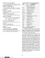
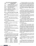
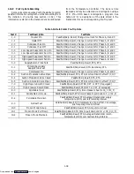
(Refer to Table 1-10.)
d. Store at least one years worth of data based on
continuous unit operation at factory default settings.
Factory default settings are:
One (1) hour logging interval.
Configured for two (2) probes.
e. Record DataCorder/Network generated data
and events as follows:
--- Container ID Change
--- Controller S/W Upgrade
--- Controller Replacement
--- DataCorder Alarm Activity
--- DataCorder Battery Low (Battery Pack)
--- DataCorder S/W Upgrade
--- Data Retrieval
--- Defrost Start
--- Defrost End
--- Dehumidification Start
--- Dehumidification End
--- Controller Alarm Activity
--- Controller Communication Not Responding
--- Controller Communication Responding
--- Power Loss (w/wo battery backup)
--- Power Up (w/wo battery backup)
--- “Auto 1” Pre-Trip Start
--- “Auto 1” Pre-Trip End
--- Remote Probe Temperatures in the Container
(USDA Cold treatment and Cargo
probe recording)
--- Return Air Temperature
--- Set Point Change
--- Supply Air Temperature
--- Real Time Clock (RTC) Battery
(Internal Battery) Replaced
--- Real Time Clock (RTC) Modification
--- Trip Start
--- Economy Mode Start
--- Economy Mode End
--- “Auto 2” Pre-Trip Start
--- “Auto 2” Pre-Trip End
Downloaded from
Содержание 69NT40-489
Страница 1: ...Model 69NT40 489 T 259 Rev F Downloaded from ManualsNet com search engine ...
Страница 100: ...5 9 Figure 5 4 Electrical Wiring Diagram Model 69NT40 489 2 Sheet 2 of 2 Downloaded from ManualsNet com search engine ...
Страница 141: ...5 50 Figure 5 25 Electrical Schematic Model 69NT40 489 19 Sheet 1 of 2 Downloaded from ManualsNet com search engine ...
Страница 142: ...5 51 Figure 5 25 Electrical Schematic Model 69NT40 489 19 Sheet 2 of 2 Downloaded from ManualsNet com search engine ...
Страница 149: ...5 58 Figure 5 29 Electrical Schematic Models 69NT40 489 50 Sheet 1 of 2 Downloaded from ManualsNet com search engine ...
Страница 150: ...5 59 Figure 5 29 Electrical Schematic Models 69NT40 489 50 Sheet 2 of 2 Downloaded from ManualsNet com search engine ...
Страница 157: ...5 66 Figure 5 33 Electrical Schematic Models 69NT40 489 62 Sheet 1 of 2 Downloaded from ManualsNet com search engine ...
Страница 158: ...5 67 Figure 5 33 Electrical Schematic Models 69NT40 489 62 Sheet 2 of 2 Downloaded from ManualsNet com search engine ...
Страница 161: ...5 70 Figure 5 35 Electrical Schematic Models 69NT40 489 78 Sheet 1 of 2 Downloaded from ManualsNet com search engine ...
Страница 162: ...5 71 Figure 5 35 Electrical Schematic Models 69NT40 489 78 Sheet 2 of 2 Downloaded from ManualsNet com search engine ...
Страница 165: ...5 74 Figure 5 37 Electrical Schematic Models 69NT40 489 80 Sheet 1 of 2 Downloaded from ManualsNet com search engine ...
Страница 166: ...5 75 Figure 5 37 Electrical Schematic Models 69NT40 489 80 Sheet 2 of 2 Downloaded from ManualsNet com search engine ...
Страница 169: ...5 78 Figure 5 39 Electrical Schematic Models 69NT40 489 30 31 Sheet 1 of 2 Downloaded from ManualsNet com search engine ...
Страница 170: ...5 79 Figure 5 39 Electrical Schematic Models 69NT40 489 30 31 Sheet 2 of 2 Downloaded from ManualsNet com search engine ...

