1-40
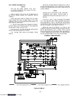
1.16 HUMIDITY CONTROL (OPTIONAL)
NOTE
The supply air must be in-range for the humidity
circuit to energize.
The humidity control is designed to operate when
transporting a chill load, controller set above ---10
_
C
(+14
_
F) or ---5
_
C (+23
_
F) optionally, and is locked out
when the controller is set below ---10
_
C or ---5
_
C
(optionally).
Code Cd33 is factory set at 70% R.H. for units
equipped with a humidity sensor and configured for
humidity sensing. When humidity configuration is
“OFF”, this means either the unit is not equipped with a
humidity sensor or has not been configured for humidity
control. (See Cd33, page 1---24)
a. The humidity control will be in operation if:
1. Unit is equipped with a humidity sensor and
configured for dehumidification.
2. Supply air is in-range (in-range light
illuminated).
3. Dehumidification control code Cd33 is properly
set for desired R.H.
4. Controller is set above ---10
_
C (+14
_
F) or ---5
_
C
(+23
_
F) optionally.
5. Container relative humidity is above 2% of code
Cd33 setting.
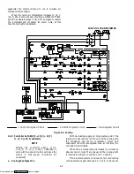
If all 5 factors are met, the humidity control circuit
energizes the heaters and heat light.
b. For testing purposes:
WARNING
Beware of rotating evaporator fan when
conducting following test.
1. Set the controller set pointer within 2
_
C (3.6
_
F)
of container supply air temperature.
2. Change the set point of code Cd33 to test the
heaters. They should be energized (heat light ON) and
then reset code Cd33 to the desired level.
1.17 NITROGEN FEED (OPTIONAL)
The purpose of the nitrogen feed option is to provide
a way to inject nitrogen into the air stream of the unit.
This is done by connecting a nitrogen line to the
quick-connect on the front of the unit, with a 1/4” nipple
conforming to the MIL-C-4109. The nitrogen can then be
feed into the unit. The unit is equipped with a pressure
relief device to prevent the pressure in the container from
exceeding two inches water gauge.
WARNING
Do not use a nitrogen feed inlet pressure higher
than 35 PSI.
Downloaded from
Содержание 69NT40-489
Страница 1: ...Model 69NT40 489 T 259 Rev F Downloaded from ManualsNet com search engine ...
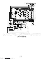
Страница 100: ...5 9 Figure 5 4 Electrical Wiring Diagram Model 69NT40 489 2 Sheet 2 of 2 Downloaded from ManualsNet com search engine ...
Страница 141: ...5 50 Figure 5 25 Electrical Schematic Model 69NT40 489 19 Sheet 1 of 2 Downloaded from ManualsNet com search engine ...
Страница 142: ...5 51 Figure 5 25 Electrical Schematic Model 69NT40 489 19 Sheet 2 of 2 Downloaded from ManualsNet com search engine ...
Страница 149: ...5 58 Figure 5 29 Electrical Schematic Models 69NT40 489 50 Sheet 1 of 2 Downloaded from ManualsNet com search engine ...
Страница 150: ...5 59 Figure 5 29 Electrical Schematic Models 69NT40 489 50 Sheet 2 of 2 Downloaded from ManualsNet com search engine ...
Страница 157: ...5 66 Figure 5 33 Electrical Schematic Models 69NT40 489 62 Sheet 1 of 2 Downloaded from ManualsNet com search engine ...
Страница 158: ...5 67 Figure 5 33 Electrical Schematic Models 69NT40 489 62 Sheet 2 of 2 Downloaded from ManualsNet com search engine ...
Страница 161: ...5 70 Figure 5 35 Electrical Schematic Models 69NT40 489 78 Sheet 1 of 2 Downloaded from ManualsNet com search engine ...
Страница 162: ...5 71 Figure 5 35 Electrical Schematic Models 69NT40 489 78 Sheet 2 of 2 Downloaded from ManualsNet com search engine ...
Страница 165: ...5 74 Figure 5 37 Electrical Schematic Models 69NT40 489 80 Sheet 1 of 2 Downloaded from ManualsNet com search engine ...
Страница 166: ...5 75 Figure 5 37 Electrical Schematic Models 69NT40 489 80 Sheet 2 of 2 Downloaded from ManualsNet com search engine ...
Страница 169: ...5 78 Figure 5 39 Electrical Schematic Models 69NT40 489 30 31 Sheet 1 of 2 Downloaded from ManualsNet com search engine ...
Страница 170: ...5 79 Figure 5 39 Electrical Schematic Models 69NT40 489 30 31 Sheet 2 of 2 Downloaded from ManualsNet com search engine ...

