1-37
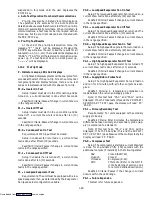
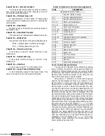
Table 1-10. DataCorder Alarm Indications
CODE
ALARM DESCRIPTION
Press ALT. MODE to access
AL70
Recorder Supply Temperature Out of Range
AL71
Recorder Return Temperature Out of Range
AL72 --- 74
USDA Temperature Out of Range
AL75
Cargo Probe Out of Range
AL76, 77
Voltage Sensors 1 -- 3 Out of Range
AL78 --- 85
Network Sensors 1 -- 3 Out of Range
AL86 --- 90
Errors 1 -- 5 Out of Range
AL91
DataCorder Alarm Queue Full
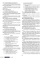
Alarm 70 --- Recorder Supply Temperature Out of Range
The supply air probe temperature is outside of its
specified range.
Alarm 71 --- Recorder Return Temperature Out of Range
The return air probe temperature is outside of its
specified range.
Alarm 72 --- 74 --- USDA Temperature Out of Range
The USDA probe temperature reading is outside of
its specified range.
Alarm 75 --- Cargo Probe Out of Range
The cargo probe temperature reading is outside of its
specified range.
Alarm 76, 77 --- Voltage Sensors 1 & 2 Out of Range
Future expansion.
Alarm 78 --- 85 --- Network Sensors Out of Range
The network sensor is outside of its specified range.
Alarm 86 --- 90 --- Errors 1 --- 5
There are technical difficulties within the DataCord-
er module, contact your local Carrier Transicold Field
Service Representative.
Alarm 91 --- DataCorder Alarm Queue Full
The DataCorder alarm queue is determined to be
full (8 alarms).
For Revision Level 2005 and above:
The DataCorder alarms for the USDA and cargo
probes are configurable using the interrogation program
or via configuration card. There are four new configura-
tion variables for the DataCorder. They are listed below
in with their descriptions and selection values:
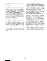
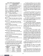
Table 1-11. DataCorder Alarm Configurations
Configuration
Variable
Description
Selection
Values
dCF07
USDA 1
Auto,On,Off
dCF08
USDA 2
Auto,On,Off
dCF09
USDA 3
Auto,On,Off
dCF10
Cargo Probe
Auto,On,Off
The default configuration for the four probes is
“Auto”. If the alarms are configured as “Auto”, and then if
all of the probes are missing (i.e., appear open circuited
to the DataCorder), then no alarms are activated. As
soon as one of the probes is installed (plugged into the
receptacle), then all of the alarms are enabled and the
remaining probes that are not installed will give active
alarm indications. This was done to assist those users who
wish to keep their DataCorder configured for USDA
recording , however, do not wish to install the probes for
every trip.
If a probe alarm is configured to be “On”, then its
associated alarm is always enabled. This means that, as
long as the probe remains in-circuit (plugged in) the
alarm will not be activated. Probes with this configuration
have alarms that act like the alarms for the supply and
return recorder sensors. It is presumed that normal
operation includes the probe in question.
If a probe alarm is configured to be “Off”, then the
alarm for this probe is always disabled. This means that it
is not possible to activate the respective alarm for this
probe no matter what the circumstance.
1.14.7 USDA/ Message Trip Comment
A special case event is supported for allowing the
user to enter comments for a (USDA or any message) trip
recording. The comments will be received from the
interrogator and have a maximum length of 78
characters. Only one comment will be recorded per day.
In the event that multiple comments occur, then only the
last will be saved.
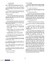
1.14.8 USDA Recording
A special type of recording is provided for USDA
cold treatment purposes. Cold treatment recording
requires that three remote probes are placed in the cargo
at various locations. (An optional fourth cargo probe is
also available.) Provision is made to connect these probes
to the DataCorder via receptacles located at the rear
left-hand side of the unit. Four (Five, on some units)
receptacles are provided. Four (three pin) are for the
probes and one (five pin) is provided for the Interrogator.
All receptacles are sized to accept a Deutsch HD16-5-16S
size plug with a tricam coupling locking device (with the
exception of models 69NT40-489-50 and -489-62). The
DataCorder inputs are designed to accept a two wire
thermistor probe.
A label on the back panel of the unit shows which
receptacle is used for each probe. The USDA #1, #2 and
#3 probes (and possibly the optional Cargo probe) are
installed in their receptacles.
The DataCorder can record up to six probe
temperatures (supply, return, USDA #1, #2, #3 and an
optional cargo probe) every minute over the hour
interval to calculate an average temperature for
recording.
The standard DataCorder report displays the supply
and return air temperatures. The cold treatment report
displays USDA #1, #2, #3 and the return air
temperature. Cold treatment recording is backed up by a
battery so recording will continue if AC power is lost.
Downloaded from
Содержание 69NT40-489
Страница 1: ...Model 69NT40 489 T 259 Rev F Downloaded from ManualsNet com search engine ...
Страница 100: ...5 9 Figure 5 4 Electrical Wiring Diagram Model 69NT40 489 2 Sheet 2 of 2 Downloaded from ManualsNet com search engine ...
Страница 141: ...5 50 Figure 5 25 Electrical Schematic Model 69NT40 489 19 Sheet 1 of 2 Downloaded from ManualsNet com search engine ...
Страница 142: ...5 51 Figure 5 25 Electrical Schematic Model 69NT40 489 19 Sheet 2 of 2 Downloaded from ManualsNet com search engine ...
Страница 149: ...5 58 Figure 5 29 Electrical Schematic Models 69NT40 489 50 Sheet 1 of 2 Downloaded from ManualsNet com search engine ...
Страница 150: ...5 59 Figure 5 29 Electrical Schematic Models 69NT40 489 50 Sheet 2 of 2 Downloaded from ManualsNet com search engine ...
Страница 157: ...5 66 Figure 5 33 Electrical Schematic Models 69NT40 489 62 Sheet 1 of 2 Downloaded from ManualsNet com search engine ...
Страница 158: ...5 67 Figure 5 33 Electrical Schematic Models 69NT40 489 62 Sheet 2 of 2 Downloaded from ManualsNet com search engine ...
Страница 161: ...5 70 Figure 5 35 Electrical Schematic Models 69NT40 489 78 Sheet 1 of 2 Downloaded from ManualsNet com search engine ...
Страница 162: ...5 71 Figure 5 35 Electrical Schematic Models 69NT40 489 78 Sheet 2 of 2 Downloaded from ManualsNet com search engine ...
Страница 165: ...5 74 Figure 5 37 Electrical Schematic Models 69NT40 489 80 Sheet 1 of 2 Downloaded from ManualsNet com search engine ...
Страница 166: ...5 75 Figure 5 37 Electrical Schematic Models 69NT40 489 80 Sheet 2 of 2 Downloaded from ManualsNet com search engine ...
Страница 169: ...5 78 Figure 5 39 Electrical Schematic Models 69NT40 489 30 31 Sheet 1 of 2 Downloaded from ManualsNet com search engine ...
Страница 170: ...5 79 Figure 5 39 Electrical Schematic Models 69NT40 489 30 31 Sheet 2 of 2 Downloaded from ManualsNet com search engine ...

