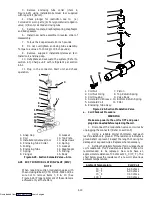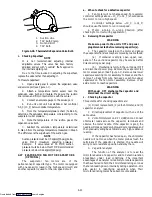
4-23
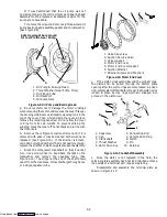
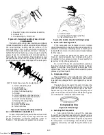
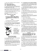
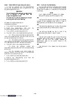
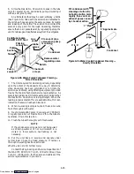
3. Tilt the top of the module forward and insert the
bottom of the module into the slot provided, then tilt back,
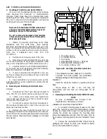
tighten the mounting screw (see Figure 4-29, item 1).
4. Connect the front wire harness connectors (MD &
KC) to the DataCORDER (item 4).
Removal:
Remove the DataCORDER module by reversing the
above steps. If the user is not immediately replacing the
DataCORDER, make sure to cut the wire tie holding the
connector mounting plate to the wire harness and then
assemble plate and connector to mount to the control box.
Installation for units with DataCORDER:
1. Repeat the installation steps above, except for
step one.
2. Place the old DataCORDER into the same
packaging that accompanied the new module.
Make sure
that you package it in the exact same manner.
NOTE
This packaging has been designed to protect the
DataCORDER
from
both
physical
and
electrostatic discharge damage during storage and
transit.
Torque values for item 1 are 0.23 mkg (20
inch-pounds), and 0.12 mkg (10 inch-pounds) for all
connectors.
4.28.1 Controller Programming Procedure
To load new software into the Controller module, the
programming
card
is
inserted
into
the
programming/software port.
WARNING
The unit must be OFF whenever a programming
card is inserted or removed from the
programming/software port.
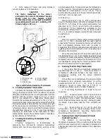
The metal door on the programming card must
be facing to the left when inserting.
Procedure for loading Operational Software:
a. Turn unit OFF, via start-stop switch (ST).
b. Insert the programming card, for Operational
Software, into the programming/software port. (See
Figure 4-29)
c. Turn unit ON, via start-stop switch (ST).
d. The Display module will read:
(1.) If the correct card is being used the digital
display will alternate back and forth between the
messages “rEV XXXX” and “Press EntR”.
(2.) If a defective card is being used: the
Display will blink the message “bAd CArd”. (Turn
start-stop switch OFF and remove the card.)
e. Press the ENTER key on the keypad.
f. The Display will show the message “Pro SoFt”. This
message will last for up to one minute.
g. The Display module will read:
(1.) When
the
software
loading
has
successfully completed: the Display will show the
message “Pro donE”.
(2.) If a problem occurs while loading the
software: the Display will blink the message “Pro FAIL”
or “bad 12V”. (Turn start-stop switch OFF and remove
the card.)
h. Turn unit OFF, via start-stop switch (ST).
i.
Remove the programming card from the
programming/software port.
j.
Turn unit ON, via start-stop switch (ST).
Procedure for loading Configuration Software:
a. Turn unit OFF, via start-stop switch (ST).
b. Insert the programming card, for Configuration
Software, into the programming/software port. (See
Figure 4-29)
c. Turn unit ON, via start-stop switch (ST).
d. The Display module will read:
(1.) If the correct card is being used the digital
display will show “nt40” on the left LCD display and
“489XX” on the right LCD display. “XX” will indicate
the dash number for a given unit model number (i.e., For
the unit 69NT40-489-62, the left display will show “nt40”
and the right display will show “48962”.)
(2.) If a defective card is being used: the
Display will blink the message “bAd CArd”. (Turn
start-stop switch OFF and remove the card.)
e. Press the ENTER key on the keypad.
f. The Display will show the message “EEPrM LOAd”.
This message will last for up to one minute.
g. The Display module will read:
(1.) When
the
software
loading
has
successfully completed: the Display will show the
message “Cnf donE”.
(2.) If a problem occurs while loading the
software: the Display will blink the message “Pro FAIL”
or “bad 12V”. (Turn start-stop switch OFF and remove
the card.)
h. Turn unit OFF, via start-stop switch (ST).
i.
Remove the programming card from the
programming/software port.
j.
Turn unit ON, via start-stop switch (ST).
Downloaded from
Содержание 69NT40-489
Страница 1: ...Model 69NT40 489 T 259 Rev F Downloaded from ManualsNet com search engine ...
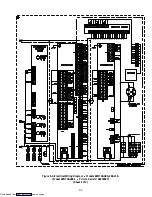
Страница 100: ...5 9 Figure 5 4 Electrical Wiring Diagram Model 69NT40 489 2 Sheet 2 of 2 Downloaded from ManualsNet com search engine ...
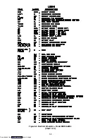
Страница 141: ...5 50 Figure 5 25 Electrical Schematic Model 69NT40 489 19 Sheet 1 of 2 Downloaded from ManualsNet com search engine ...
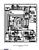
Страница 142: ...5 51 Figure 5 25 Electrical Schematic Model 69NT40 489 19 Sheet 2 of 2 Downloaded from ManualsNet com search engine ...
Страница 149: ...5 58 Figure 5 29 Electrical Schematic Models 69NT40 489 50 Sheet 1 of 2 Downloaded from ManualsNet com search engine ...
Страница 150: ...5 59 Figure 5 29 Electrical Schematic Models 69NT40 489 50 Sheet 2 of 2 Downloaded from ManualsNet com search engine ...
Страница 157: ...5 66 Figure 5 33 Electrical Schematic Models 69NT40 489 62 Sheet 1 of 2 Downloaded from ManualsNet com search engine ...
Страница 158: ...5 67 Figure 5 33 Electrical Schematic Models 69NT40 489 62 Sheet 2 of 2 Downloaded from ManualsNet com search engine ...
Страница 161: ...5 70 Figure 5 35 Electrical Schematic Models 69NT40 489 78 Sheet 1 of 2 Downloaded from ManualsNet com search engine ...
Страница 162: ...5 71 Figure 5 35 Electrical Schematic Models 69NT40 489 78 Sheet 2 of 2 Downloaded from ManualsNet com search engine ...
Страница 165: ...5 74 Figure 5 37 Electrical Schematic Models 69NT40 489 80 Sheet 1 of 2 Downloaded from ManualsNet com search engine ...
Страница 166: ...5 75 Figure 5 37 Electrical Schematic Models 69NT40 489 80 Sheet 2 of 2 Downloaded from ManualsNet com search engine ...
Страница 169: ...5 78 Figure 5 39 Electrical Schematic Models 69NT40 489 30 31 Sheet 1 of 2 Downloaded from ManualsNet com search engine ...
Страница 170: ...5 79 Figure 5 39 Electrical Schematic Models 69NT40 489 30 31 Sheet 2 of 2 Downloaded from ManualsNet com search engine ...

