1-34
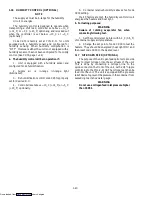
d. DataCorder Diagnostics
The DataCorder start up diagnostics processing will
occur each time there is a power up or after a hardware
reset. This processing will test the DataCorder hardware
for proper operation. If any critical test fails, then
depending on the LED fail code display decision in the
DataCorder header, the FAIL LED will first be on for 10
seconds then flash the test code three times to indicate
what test failed (i.e., if the timer test fails the FAIL LED
will come on at first for ten seconds, then it will quickly
flash on/off four times, three times in a row) The
DataCorder will then reset itself and start again. The
following tests will be run:
--- Data Memory Test (code 1)
--- Program Memory Test (code 2)
--- Watchdog Timer Test (code 3)
--- Timer Test (code 4)
--- Programmable Counters Test (code 5)
--- Analog to Digital Converters Test (code 6)
e. DataCorder Battery Pack Test
If the DataCorder has the optional battery pack
backup, then the battery voltage will be tested once every
fifteen minutes if it is low or dead. If the battery voltage is
less than 6.0V then the battery voltage is considered low.
An event will be generated when the battery voltage
transitions from good to low or bad indicating that the
battery voltage is low.
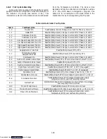
f. Trip Start Processing
For the user to initiate a Trip Start, press the ALT.
MODE key and select Code dC30, then depressing the
ENTER key for 5 seconds to initiate Trip Start. The right
display will display the message “StArt” for five seconds
and a Trip Start event code will be generated. Trip start
may also be initiated via communications using the
interrogation program.
g. Display vs. Configuration Codes
The DataCorder contains two types of display codes;
Display and Configuration. Display codes will display
parameter values, but will not let them be modified.
Configuration codes can be modified via the interrogator
or with the insertion of a new configuration software
card.
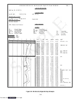
h. Data Recording Mode
The DataCorder recording mode is labeled as
Standard. To examine an example of a report using a
standard configuration, see Figure 1-12.
Generic Mode:
The generic recording mode is used for special
applications (i.e., CTD Controlled Atmosphere option).
Standard Mode:
The standard recording mode allows the user to
configure the DataCorder to monitor data using one of 8
standard configurations. These are as follows:
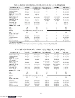
1. 2 sensors (dCF02 = 2) --- 2 thermistor inputs
(supply & return)
2. 5 sensors (dCF02 = 5) --- 2 thermistor inputs
(supply & return)
--- 3 usda thermistor inputs
3. 6 sensors (dCF02 = 6) --- 2 thermistor inputs
(supply & return)
--- 3 usda thermistor inputs
--- 1 humidity input
4. 9 sensors (dCF02 = 9) --- 2 thermistor inputs
(supply & return)
--- 3 usda thermistor inputs
--- 3 CA inputs
--- 1 humidity input
5. 3 sensors (dCF02 = 24) --- 2 thermistor inputs
(supply & return)
--- 1 cargo probe
6. 6 sensors (dCF02 = 54) --- 2 thermistor inputs
(supply & return)
--- 3 usda thermistor inputs
--- 1 cargo probe
7. 7 sensors (dCF02 = 64) --- 2 thermistor inputs
(supply & return)
--- 3 usda thermistor inputs
--- 1 humidity input
--- 1 cargo probe
8. 10 sensors (dCF02 = 94) --- 2 thermistor inputs
(supply & return)
--- 3 usda thermistor inputs
--- 3 CA inputs
--- 1 humidity input
--- 1 cargo probe
The 6 thermistor inputs will be DataCorder inputs.
The 3 Controlled Atmosphere inputs will be read over a
network from the optional Controlled Atmosphere
module. The humidity input will be read from the
controller module.
In addition, if no Controller alarms are active, the
most recent active DataCorder alarm will be displayed on
the Controller display alternately with set point.
i.
DataCorder Alarm History List
The DataCorder contains a buffer of up to 8 alarms.
The list may be displayed by pressing the ALARM LIST
key. The alarm history keypad and display processing will
be the same as the controller module. The format of an
alarm history display entry is as follows:
Left Display:
“dALnn” where nn = the alarm history entry 01-08
Right Display:
“xA nn” where x = ’I’ (inactive) or ’A’ (active)
Or:
“--- --- --- ---” if no alarms are currently in the alarm
history list
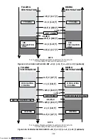
j.
Alarm Processing
Downloaded from
Содержание 69NT40-489
Страница 1: ...Model 69NT40 489 T 259 Rev F Downloaded from ManualsNet com search engine ...
Страница 100: ...5 9 Figure 5 4 Electrical Wiring Diagram Model 69NT40 489 2 Sheet 2 of 2 Downloaded from ManualsNet com search engine ...
Страница 141: ...5 50 Figure 5 25 Electrical Schematic Model 69NT40 489 19 Sheet 1 of 2 Downloaded from ManualsNet com search engine ...
Страница 142: ...5 51 Figure 5 25 Electrical Schematic Model 69NT40 489 19 Sheet 2 of 2 Downloaded from ManualsNet com search engine ...
Страница 149: ...5 58 Figure 5 29 Electrical Schematic Models 69NT40 489 50 Sheet 1 of 2 Downloaded from ManualsNet com search engine ...
Страница 150: ...5 59 Figure 5 29 Electrical Schematic Models 69NT40 489 50 Sheet 2 of 2 Downloaded from ManualsNet com search engine ...
Страница 157: ...5 66 Figure 5 33 Electrical Schematic Models 69NT40 489 62 Sheet 1 of 2 Downloaded from ManualsNet com search engine ...
Страница 158: ...5 67 Figure 5 33 Electrical Schematic Models 69NT40 489 62 Sheet 2 of 2 Downloaded from ManualsNet com search engine ...
Страница 161: ...5 70 Figure 5 35 Electrical Schematic Models 69NT40 489 78 Sheet 1 of 2 Downloaded from ManualsNet com search engine ...
Страница 162: ...5 71 Figure 5 35 Electrical Schematic Models 69NT40 489 78 Sheet 2 of 2 Downloaded from ManualsNet com search engine ...
Страница 165: ...5 74 Figure 5 37 Electrical Schematic Models 69NT40 489 80 Sheet 1 of 2 Downloaded from ManualsNet com search engine ...
Страница 166: ...5 75 Figure 5 37 Electrical Schematic Models 69NT40 489 80 Sheet 2 of 2 Downloaded from ManualsNet com search engine ...
Страница 169: ...5 78 Figure 5 39 Electrical Schematic Models 69NT40 489 30 31 Sheet 1 of 2 Downloaded from ManualsNet com search engine ...
Страница 170: ...5 79 Figure 5 39 Electrical Schematic Models 69NT40 489 30 31 Sheet 2 of 2 Downloaded from ManualsNet com search engine ...

