1-14
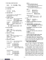
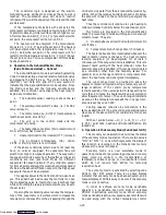
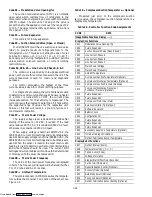
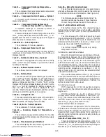
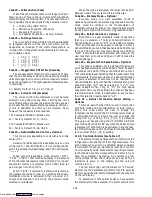
Table 1-3. Safety and Protective Devices
UNSAFE CONDITIONS
SAFETY DEVICES
DEVICE SETTING
1. Excessive current draw
1. Circuit Breaker (CB-1) ---
Manual Reset
1. Trips at 29 amps
(460 VAC)
1. Circuit Breaker (CB-2) ---
Manual Reset
1. Refer to paragraph 1.4.a
2. Excessive current draw on control circuit
2. Fuse (F3)
2. 15 amps
3. Excessive current draw by the controller
3. Fuse (F1 & F2)
3. 5 amps
4. Excessive current draw by
the optional DataCorder
4. Fuse (F)
4. 3 amps
5. Excessive condenser fan motor
winding temperature
5. Internal Protection (IP-CM) ---
Automatic Reset
5. N/A
6. Excessive compressor motor winding
temperature
6. Internal Protector (IP-CP) ---
Automatic Reset
6. N/A
7. Excessive evaporator fan motor(s)
winding temperature
7. Internal Protector(s) (IP-EM) ---
Automatic Reset
7. N/A
8. Abnormal pressures in the high
refrigerant side
8. Fusible Plug
8a. Rupture Disc
8. Refer to section 1.3.i.
8a. Refer to section 1.3.j.
9. Abnormally high discharge pressure
9. High Pressure Switch
9. Opens at 25 kg/cm
@
(350 psig)
10. Excessive evaporator motor
transformer or power (auto)
transformer winding temperature
10. Internal Protector (IP-Trans) ---
Automatic Reset
10. Opens at 178
¦
5
_
C
(350
¦
10
_
F)
Closes at 150
¦
7
_
C
(300
¦
12
_
F)
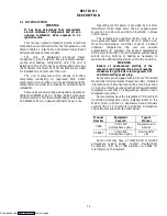
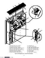
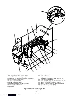
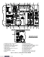
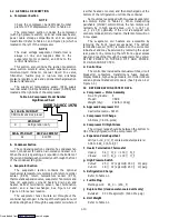
1.7 SAFETY AND PROTECTIVE DEVICES
Unit components are protected from damage by
safety and protective devices listed in Table 1-3. These
devices monitor the unit operating conditions and open a
set of electrical contacts when an unsafe condition
occurs.
Open safety switch contacts of one or more of the
following devices IP-CP, HPS, or IP-Trans (Auto) will shut
down the compressor.
Open safety switch contacts of device IP-CM will shut
down the condenser fan motor.
The entire refrigeration unit will shut down if one of
the following safety devices open: (a) Circuit Breaker(s)
or; (b) Fuse (F3/15A) or; (c) Evaporator Fan Motor
Internal Protector(s) --- (IP-EM).
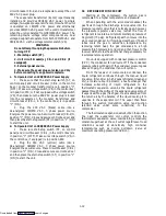
1.8 FRESH AIR MAKEUP VENT
The purpose of the vent is to provide ventilation for
commodities that require fresh air circulation and
must
be closed
when transporting frozen foods.
Air exchange depends on static pressure differential
which will vary depending on the container and how the
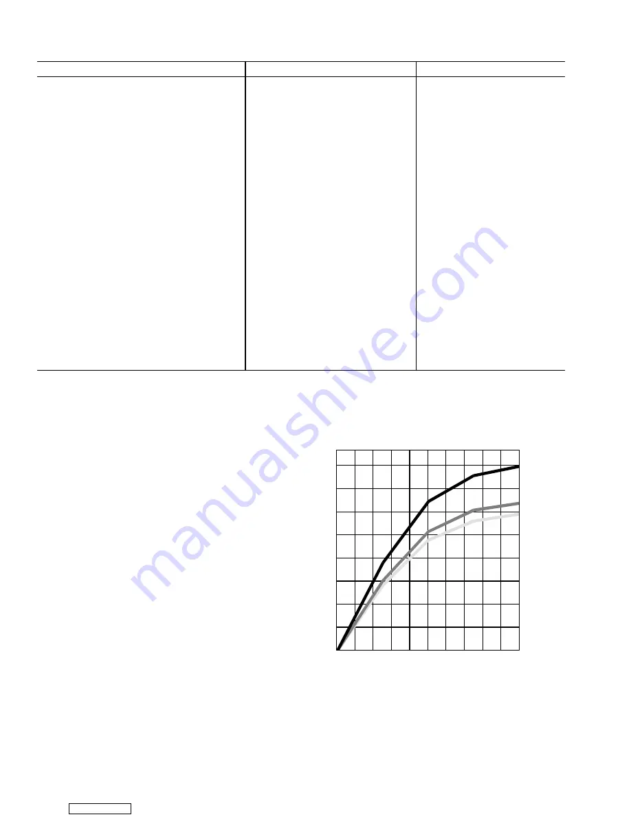
container is loaded. The chart above gives air exchange
values for an empty container. Higher values can be
expected for a fully loaded container.
0
30
60
90
120
150
180
210
240
0
10 20 30 40 50 60 70 80 90 100
AIR
FLOW
(CMH)
1-
!
/
2
”
PERCENT OPEN
69NT40 FRESH AIR MAKEUP
T-BAR
2-
%
/
8
”
3”
T-BAR
T-BAR
ZERO EXTERNAL STATIC PRESSURE, 50HZ POWER
For 60HZ operation multiply curves by 1.2
a. Full Open or Closed Positions
Maximum air flow is achieved by loosening the wing
nuts and moving the cover to the maximum open position
(100% position). The closed position is 0% air flow
position.
Downloaded from
Содержание 69NT40-489
Страница 1: ...Model 69NT40 489 T 259 Rev F Downloaded from ManualsNet com search engine ...
Страница 100: ...5 9 Figure 5 4 Electrical Wiring Diagram Model 69NT40 489 2 Sheet 2 of 2 Downloaded from ManualsNet com search engine ...
Страница 141: ...5 50 Figure 5 25 Electrical Schematic Model 69NT40 489 19 Sheet 1 of 2 Downloaded from ManualsNet com search engine ...
Страница 142: ...5 51 Figure 5 25 Electrical Schematic Model 69NT40 489 19 Sheet 2 of 2 Downloaded from ManualsNet com search engine ...
Страница 149: ...5 58 Figure 5 29 Electrical Schematic Models 69NT40 489 50 Sheet 1 of 2 Downloaded from ManualsNet com search engine ...
Страница 150: ...5 59 Figure 5 29 Electrical Schematic Models 69NT40 489 50 Sheet 2 of 2 Downloaded from ManualsNet com search engine ...
Страница 157: ...5 66 Figure 5 33 Electrical Schematic Models 69NT40 489 62 Sheet 1 of 2 Downloaded from ManualsNet com search engine ...
Страница 158: ...5 67 Figure 5 33 Electrical Schematic Models 69NT40 489 62 Sheet 2 of 2 Downloaded from ManualsNet com search engine ...
Страница 161: ...5 70 Figure 5 35 Electrical Schematic Models 69NT40 489 78 Sheet 1 of 2 Downloaded from ManualsNet com search engine ...
Страница 162: ...5 71 Figure 5 35 Electrical Schematic Models 69NT40 489 78 Sheet 2 of 2 Downloaded from ManualsNet com search engine ...
Страница 165: ...5 74 Figure 5 37 Electrical Schematic Models 69NT40 489 80 Sheet 1 of 2 Downloaded from ManualsNet com search engine ...
Страница 166: ...5 75 Figure 5 37 Electrical Schematic Models 69NT40 489 80 Sheet 2 of 2 Downloaded from ManualsNet com search engine ...
Страница 169: ...5 78 Figure 5 39 Electrical Schematic Models 69NT40 489 30 31 Sheet 1 of 2 Downloaded from ManualsNet com search engine ...
Страница 170: ...5 79 Figure 5 39 Electrical Schematic Models 69NT40 489 30 31 Sheet 2 of 2 Downloaded from ManualsNet com search engine ...

