1-36
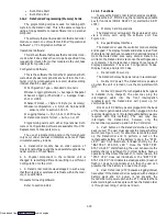
Code dC 26, 27 --- S/N, Left 4, Right 4
The DataCorder serial number consists of 8 charac-
ters. Code 26 contains the first 4 characters. Code 27
contains the last 4 characters.
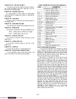
Code dC 28 --- Minimum Days Left
An approximation of the number of logging days
remaining until the DataCorder starts to overwrite the
existing data.
Code dC 29 --- Days Stored
Number of days of data that are currently stored in
the DataCorder.
Code dC 30 --- Date of last Trip start
The date when a Trip Start was initiated by the user.
Code dC 31 --- Battery Test
Shows the current status of the optional battery pack.
PASS --- Battery pack is sufficiently charged.
FAIL --- Battery pack voltage is low.
Code dC 32 --- Time: Hour, Minute
Current time on the RTC (Real Time Clock) in the
DataCorder.
Code dC 33 --- Date: Month, Day
Current date (month and day) on the RTC in the
DataCorder.
Code dC 34 --- Date: Year
Current year on the RTC in the DataCorder.
Code dC 35 --- Cargo Probe Calibration Value
Current calibration value for the Cargo Probe. This
value is an input via the interrogation program.
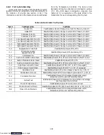
Table 1-9. DataCorder Function Code Assignments
CODE
DESCRIPTION
(Inapplicable Functions Display --------)
Press ALT. MODE to access
dC 1
Recorder Supply Temperature
dC 2
Recorder Return Temperature
dC 3 -- 5
USDA 1,2,3 Temperatures
dC 6 -- 13
Network Sensors 1-8
dC 14
Cargo Probe Temperature
dC 15 -- 16
Voltage Sensors 1,2
dC 17, 18
Discrete Inputs 1-6
dC 19
Discrete Output
dC 20 -- 24
Temperature Sensors 1-5 Calibration
dC 25
Software Revision #
dC 26, 27
S/N, Left 4, Right 4
dC 28
Minimum Days Left
dC 29
Days Stored
dC 30
Date of last Trip start
dC 31
Battery Test
dC 32
Time: Hour, Minute
dC 33
Date: Month, Day
dC 34
Date: Year
dC 35
Cargo Probe Calibration Value
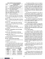
1.14.6 DataCorder Alarm Codes
The Alarm List Display Mode is entered by pressing
the ALT. MODE & ALARM LIST keys while in Set Point
Selection or Default Display mode. The user will be able
to display any alarms archived in the Alarm Queue. If no
alarms, other than those related to the EEprom, are
active, the Alarm Queue may be cleared.
When the ALT. MODE & ALARM LIST keys are
pushed, the left display will show AL# where # is the
alarms number in the queue and the right display will
shown AAXX, if the alarm is active, where XX is the
alarm number or IAXX, if the alarm is inactive. The user
can look through the alarm queue by depressing the UP
ARROW key. At the end of the alarm list, if any of the
alarm(s) in the list is active, END is displayed. If all the
alarms in the list are inactive, then at the end of the alarm
list, CLEAr is displayed. (The exception to this rule is the
DataCorder Alarm Queue Full AL91 alarm, this alarm
does not have to go inactive in order to clear the alarm
list) At this time if the user pushes the ENTER key, then
the alarm list will clear and display “--- --- --- ---” on right
display. Another alternative for the user to get to the end
of the alarm list is by pushing the DOWN ARROW key
after the ALARM LIST key is pushed. Thus, the DOWN
ARROW key being pushed will allow the user to go
backward in the alarm list. If a user pushes the ALARM
LIST key when there are no alarms in the list, then AL is
displayed on the left display and “--- --- --- ---” on the the
right display. Upon clearing of the Alarm Queue, the
Alarm light will be turned off.
Downloaded from
Содержание 69NT40-489
Страница 1: ...Model 69NT40 489 T 259 Rev F Downloaded from ManualsNet com search engine ...
Страница 100: ...5 9 Figure 5 4 Electrical Wiring Diagram Model 69NT40 489 2 Sheet 2 of 2 Downloaded from ManualsNet com search engine ...
Страница 141: ...5 50 Figure 5 25 Electrical Schematic Model 69NT40 489 19 Sheet 1 of 2 Downloaded from ManualsNet com search engine ...
Страница 142: ...5 51 Figure 5 25 Electrical Schematic Model 69NT40 489 19 Sheet 2 of 2 Downloaded from ManualsNet com search engine ...
Страница 149: ...5 58 Figure 5 29 Electrical Schematic Models 69NT40 489 50 Sheet 1 of 2 Downloaded from ManualsNet com search engine ...
Страница 150: ...5 59 Figure 5 29 Electrical Schematic Models 69NT40 489 50 Sheet 2 of 2 Downloaded from ManualsNet com search engine ...
Страница 157: ...5 66 Figure 5 33 Electrical Schematic Models 69NT40 489 62 Sheet 1 of 2 Downloaded from ManualsNet com search engine ...
Страница 158: ...5 67 Figure 5 33 Electrical Schematic Models 69NT40 489 62 Sheet 2 of 2 Downloaded from ManualsNet com search engine ...
Страница 161: ...5 70 Figure 5 35 Electrical Schematic Models 69NT40 489 78 Sheet 1 of 2 Downloaded from ManualsNet com search engine ...
Страница 162: ...5 71 Figure 5 35 Electrical Schematic Models 69NT40 489 78 Sheet 2 of 2 Downloaded from ManualsNet com search engine ...
Страница 165: ...5 74 Figure 5 37 Electrical Schematic Models 69NT40 489 80 Sheet 1 of 2 Downloaded from ManualsNet com search engine ...
Страница 166: ...5 75 Figure 5 37 Electrical Schematic Models 69NT40 489 80 Sheet 2 of 2 Downloaded from ManualsNet com search engine ...
Страница 169: ...5 78 Figure 5 39 Electrical Schematic Models 69NT40 489 30 31 Sheet 1 of 2 Downloaded from ManualsNet com search engine ...
Страница 170: ...5 79 Figure 5 39 Electrical Schematic Models 69NT40 489 30 31 Sheet 2 of 2 Downloaded from ManualsNet com search engine ...

