1-21
algorithm. If the unit is not equipped with dual speed
evaporator fans, then economy mode perishable will
perform exactly the same as the normal control mode.
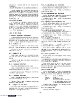
4. Operation in Bulb Mode (Code 35 set to bulb and
Code 33 selected)
Bulb mode is an extension of the dehumidification
mode and in as such, dehumidification must be enabled
by selecting a value (percentage of relative humidity) at
Code 33 before bulb mode Code 35 can be initiated.
To initiate bulb mode, use the ARROW keys to scroll
to function code Cd35 and change from “Nor” to “bulb”.
Once the bulb mode is activated, the user may then
change from the normal evaporator fan operation where
the fan speed alternates every hour between low or high
speed operation. This is done by toggling function code
Cd36 from its default of “alt” to “Lo” or “Hi”
respectively. If low speed evaporator fan operation is
selected, this gives the user the additional capability of
selecting dehumidification set points from 60 to 100%
(instead of the normal 65 to 100%).
In addition, if bulb mode is active, the user is given
the option to change the defrost termination sensor
(DTS) temperature in which defrost is terminated from
the normal 25.6
_
C (78
_
F) temperature setting to 4
_
C
(39.2
_
F) in 0.1
_
C (0.2
_
F) increments. The temperature
that the DTS temperature must go below before the
defrost interval timer begins counting down also changes
from 0
_
C to 10
_
C as the desired DTS temperature is
raised.
Bulb mode is terminated anytime:
a. Code Cd35 is set to “Nor”.
b. Code Cd33 for dehumidification is set to “Off”.
c. Anytime the user changes the set point to one
that is in the frozen range.
When bulb mode is disabled by any of the above
means,
the
evaporator
fan
operation
for
dehumidification reverts to “alt” and the DTS
termination setting resets to the normal 25.6
_
C (78
_
F).
b. Frozen range below ---10
_
C (+14
_
F) or ---5
_
C
(+23
_
F) optionally
For set points BELOW ---10
_
C (+14
_
F) or ---5
_
C
(+23
_
F) optionally, the controller maintains RETURN
air at the set temperature by the following modes of op-
eration:
1. Operation in the Conventional Mode (Code 33 OFF)
The return air probe is used for control and is so
indicated by the LED on the display board.
The Frozen temperature range is not sensitive to
minor temperature changes. The method of temperature
control employed in this range takes advantage of this
fact, to greatly improve the energy efficiency of the unit.
Temperature control in the Frozen range
at or below
---10
_
C (+14
_
F)
or ---5
_
C (+23
_
F) optionally is accom-
plished by cycling the compressor on and off as the load
demand requires.
If the return air temperature in the container drops
0.2
_
C (0.4
_
F) below the set point temperature, the
compressor is cycled off. When the temperature is
greater than 0.2
_
C (0.4
_
F) above the set point and the 3
minute time delay has been met, the compressor will
restart. The unit will always operate at full capacity which
means both the suction modulation (SMV) and suction
solenoid (SSV) valves are fully open unless suction
solenoid override or current limiting is activated. See
section 1.10 for explanation of suction solenoid override.
To prevent on/off cycling of the compressor from
occurring, a 3 minute compressor off time must be
satisfied before the compressor will restart. Under a
condition of a rapidly changing return air temperature,
the time delay may allow the return air temperature to
rise slightly more than 0.2
_
C (0.4
_
F) above the set point
temperature before the compressor can restart.
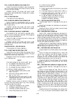
2. Operation in the Economy Mode (Code 34 OFF)
The economy mode is deactivated by selecting code
Cd34 to the “OFF” status. There is no active display
indicator that economy mode has been deactivated, and a
manual display of Cd34 is a way to be sure if the economy
mode is or is not deactivated. A second way to deactivate
economy mode is to change the set point. Once economy
mode is deactivated, the system will return to normal
control mode operations.
In order to achieve economy mode frozen operation,
a frozen set point must be selected PRIOR to activating
economy mode. When economy mode frozen is active,
the system will perform normal frozen mode operations
except that the entire refrigeration system excluding the
Controller will be turned off when the control
temperature is less than or equal to (the set point --- 2
_
C,
i.e., the set point is set at ---11
_
C and the operator
subtracts ---2
_
C, the result will equal ---13
_
C). After an
off-cycle period of 60 minutes, the unit will turn on high
speed evaporator fans for 2 minutes, and then check the
control temperature. If the control temperature is
greater than or equal to (set point + 0.2
_
C.) the unit will
restart the refrigeration system and continue to cool until
the previously mentioned off---cycle temperature criteria
is met. If however, the control temperature is less than
(set point + 0.2
_
C), the unit will turn off the evaporator
fans and restart another 60 minute off-cycle.
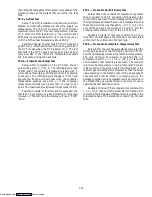
3. Operation in the Bulb Mode (Code 35 OFF)
The unit will not run in bulb mode if a frozen range
set point is selected. As described in section 1.12.4.a.4, if
a frozen set point is selected the dehumidification
evaporator fan speed reverts to alternating and the
temperature above which DTS must go during defrost
resets to 25.6
_
C (78
_
F).
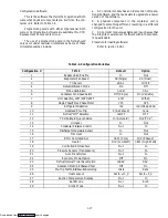
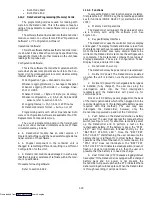
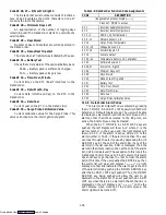
1.12.5 Controller Function Codes
There are 37 functions which the operator may
access to examine the operating status of the unit. To
access these functions, perform the following: Press the
CODE SELECT key, press an arrow key until the left
window displays the desired code number (see
Table 1-6). For the display only function codes, the right
window will display the value of this item for 5 seconds
before returning to the normal display mode. If a longer
time is desired, pressing the ENTER key will extend the
time to 30 seconds after the last pressing of the ENTER
key. Below is an explanation of all Function codes.
Downloaded from
Содержание 69NT40-489
Страница 1: ...Model 69NT40 489 T 259 Rev F Downloaded from ManualsNet com search engine ...
Страница 100: ...5 9 Figure 5 4 Electrical Wiring Diagram Model 69NT40 489 2 Sheet 2 of 2 Downloaded from ManualsNet com search engine ...
Страница 141: ...5 50 Figure 5 25 Electrical Schematic Model 69NT40 489 19 Sheet 1 of 2 Downloaded from ManualsNet com search engine ...
Страница 142: ...5 51 Figure 5 25 Electrical Schematic Model 69NT40 489 19 Sheet 2 of 2 Downloaded from ManualsNet com search engine ...
Страница 149: ...5 58 Figure 5 29 Electrical Schematic Models 69NT40 489 50 Sheet 1 of 2 Downloaded from ManualsNet com search engine ...
Страница 150: ...5 59 Figure 5 29 Electrical Schematic Models 69NT40 489 50 Sheet 2 of 2 Downloaded from ManualsNet com search engine ...
Страница 157: ...5 66 Figure 5 33 Electrical Schematic Models 69NT40 489 62 Sheet 1 of 2 Downloaded from ManualsNet com search engine ...
Страница 158: ...5 67 Figure 5 33 Electrical Schematic Models 69NT40 489 62 Sheet 2 of 2 Downloaded from ManualsNet com search engine ...
Страница 161: ...5 70 Figure 5 35 Electrical Schematic Models 69NT40 489 78 Sheet 1 of 2 Downloaded from ManualsNet com search engine ...
Страница 162: ...5 71 Figure 5 35 Electrical Schematic Models 69NT40 489 78 Sheet 2 of 2 Downloaded from ManualsNet com search engine ...
Страница 165: ...5 74 Figure 5 37 Electrical Schematic Models 69NT40 489 80 Sheet 1 of 2 Downloaded from ManualsNet com search engine ...
Страница 166: ...5 75 Figure 5 37 Electrical Schematic Models 69NT40 489 80 Sheet 2 of 2 Downloaded from ManualsNet com search engine ...
Страница 169: ...5 78 Figure 5 39 Electrical Schematic Models 69NT40 489 30 31 Sheet 1 of 2 Downloaded from ManualsNet com search engine ...
Страница 170: ...5 79 Figure 5 39 Electrical Schematic Models 69NT40 489 30 31 Sheet 2 of 2 Downloaded from ManualsNet com search engine ...


