1-35
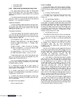
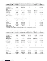
The DataCorder contains an 8 alarm history queue
which will contain the first 8 alarms detected by the
DataCorder. The alarms and their corresponding alarm
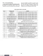
codes are specified in Table 1-10. The alarm queue will be
located in memory (EEPROM). The queue will also have
a corresponding status which will indicate whether each
alarm is currently active or inactive. If multiple
consecutive occurrences of an alarm are generated then
only the first will be stored. The queue may be cleared by
using the keypad. (If more than 8 alarms occur before the
queue is cleared, then those alarms after the first 8 will be
ignored.) In addition, AL91 will appear if the
DataCorder alarm queue is full.
1.14.4 Status LED’s
The DataCorder contains four status LEDs. These
are as follows:
--- Status/Power/Executing Code (Yellow)
--- Communication (Green)
--- Battery Status (Yellow)
--- FAIL/Alarm (Red)
Status/Power/Executing Code LED:
The Status/Power/Executing code LED indicates if
the DataCorder is powered up and executing code. The
LED will be off when power is off or the DataCorder is in
a sleep mode running off the battery. The LED will pulse
at a one second rate if code is being executed.
Communication LED:
The Communication LED will usually be off. It will
illuminate whenever there is a response from a device
which the DataCorder wishes to communicate with. If
there is a valid response to the DataCorder, this LED will
flash for five seconds. If an invalid response to a
DataCorder initiated communication occurs, then this
LED will turn on solid for five seconds.
Battery Status LED:
The Battery status LED flashes at a one second rate
when the battery voltage is greater than or equal to 6.0V.
It will be on solid when the battery voltage is less than
6.0V but greater than or equal to 4.0V. It will be off when
the battery voltage is less than 4.0V.
Fail/Alarm LED:
The Fail/Alarm LED indicates if a hardware fault or
alarm has occurred in the DataCorder. If a hardware
fault occurs, the LED will flash the fail code three times,
then the processor will reset. The fail codes and their
code numbers are defined below. Fail codes will only be
displayed on power up. If the DataCorder powers up
properly, then this LED will indicate an active alarm
condition that has been detected. The alarm LED should
turn on when an active alarm is detected, and be off when
the alarm goes inactive.
CODE
TEST
1
Data Memory Test
2
Program Memory Test
3
Watchdog Timer Test
4
Timer Test
5
Programmable Timers Test
6
Analog to Digital Converter Test
If an alarm occurs, then the LED will be on solid until
the alarm goes away. The alarm codes are listed in
Table 1-10.
The out of range values are as follows:
Thermistor Inputs:
Low limit = ---50.0 degC, High limit = 70.0 degC
Voltage Inputs:
Low limit = ---0.5 Volts, High Limit = 5.5 Volts
“AA” Batteries:
Low Battery Voltage less than 6.0V
No Battery Voltage less than 4.0V
Real Time Clock (RTC) Battery:
Low battery Voltage less than 2.5 Volts
1.14.5 DataCorder Function Codes
There are 35 functions which the operator may
access to examine the operating status of the unit. To
access these functions, perform the following: Press the
ALT. MODE & CODE SELECT keys, press an arrow key
until the left window displays the desired code number
(see Table 1-9). The right window will display the value of
this item for 5 seconds before returning to the normal
display mode. If a longer time is desired, pressing the
ENTER key will extend the time to 30 seconds after the
last pressing of the ENTER key. Below is an explanation
of all Function codes.
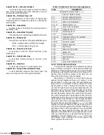
Code dC 1 --- DataCorder Supply Temperature
Current supply air temperature.
Code dC 2 --- DataCorder Return Temperature
Current return air temperature.
Code dC 3, 4, 5 --- USDA 1, 2, 3 Temperatures
Current temperatures of the three USDA probes.
Code dC 6 --- 13 --- Network Sensors 1 --- 8
Current values of the network sensors (as config-
ured). Network sensor 1 (Code 6) is the humidity sensor
and its value is obtained from the Controller once every
minute.
Code dC 14 --- Cargo Probe Temperature
Current temperature of the cargo probe.
Code dC 15, 16 --- Voltage Sensors 1, 2
Future expansion.
Code dC 17, 18 --- Discrete Input
Future expansion.
Code dC 19 --- Discrete Output
Future expansion.
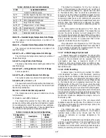
Code dC 20 --- 24 --- Temperature Sensors 1 --- 5 Calibration
Current calibration offset values for each of the five
probes; supply, return, USDA# 1,2, & 3. These values are
input via the interrogation program.
Code dC 25 --- Software Revision #
Revision # (number) of the operating software
currently in the DataCorder.
Downloaded from
Содержание 69NT40-489
Страница 1: ...Model 69NT40 489 T 259 Rev F Downloaded from ManualsNet com search engine ...
Страница 100: ...5 9 Figure 5 4 Electrical Wiring Diagram Model 69NT40 489 2 Sheet 2 of 2 Downloaded from ManualsNet com search engine ...
Страница 141: ...5 50 Figure 5 25 Electrical Schematic Model 69NT40 489 19 Sheet 1 of 2 Downloaded from ManualsNet com search engine ...
Страница 142: ...5 51 Figure 5 25 Electrical Schematic Model 69NT40 489 19 Sheet 2 of 2 Downloaded from ManualsNet com search engine ...
Страница 149: ...5 58 Figure 5 29 Electrical Schematic Models 69NT40 489 50 Sheet 1 of 2 Downloaded from ManualsNet com search engine ...
Страница 150: ...5 59 Figure 5 29 Electrical Schematic Models 69NT40 489 50 Sheet 2 of 2 Downloaded from ManualsNet com search engine ...
Страница 157: ...5 66 Figure 5 33 Electrical Schematic Models 69NT40 489 62 Sheet 1 of 2 Downloaded from ManualsNet com search engine ...
Страница 158: ...5 67 Figure 5 33 Electrical Schematic Models 69NT40 489 62 Sheet 2 of 2 Downloaded from ManualsNet com search engine ...
Страница 161: ...5 70 Figure 5 35 Electrical Schematic Models 69NT40 489 78 Sheet 1 of 2 Downloaded from ManualsNet com search engine ...
Страница 162: ...5 71 Figure 5 35 Electrical Schematic Models 69NT40 489 78 Sheet 2 of 2 Downloaded from ManualsNet com search engine ...
Страница 165: ...5 74 Figure 5 37 Electrical Schematic Models 69NT40 489 80 Sheet 1 of 2 Downloaded from ManualsNet com search engine ...
Страница 166: ...5 75 Figure 5 37 Electrical Schematic Models 69NT40 489 80 Sheet 2 of 2 Downloaded from ManualsNet com search engine ...
Страница 169: ...5 78 Figure 5 39 Electrical Schematic Models 69NT40 489 30 31 Sheet 1 of 2 Downloaded from ManualsNet com search engine ...
Страница 170: ...5 79 Figure 5 39 Electrical Schematic Models 69NT40 489 30 31 Sheet 2 of 2 Downloaded from ManualsNet com search engine ...


