1-24
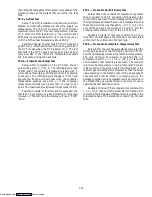
Code 29 --- Failure Action (Code)
If all of the control sensors are out of range (AL26) or
there is an AL27 failure, the unit will enter the shutdown
state defined by the failure action. The user selects one of
four possible actions as designated by a selection code:
A --- Full Cooling (SMV 100%)
B --- Partial Cooling (SMV 50% open)
C --- Evaporator Fan Only
D --- Full System Shutdown --- Factory Default
Code 30 --- In-Range Tolerance
The in-range tolerance will determine the bandwidth
of temperatures around the set point which will be
designated as in-range. If the control temperature is
in-range, the in-range light will be illuminated. There are
four possible values.
1.
¦
0.5
_
C (
¦
0.9
_
F)
2.
¦
1.0
_
C (
¦
1.8
_
F)
3.
¦
1.5
_
C (
¦
2.7
_
F)
4.
¦
2.0
_
C (
¦
3.6
_
F)
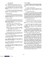
Code 31 --- Stagger Start Offset Time (Seconds)
The stagger start offset time is the amount of time
that the unit will delay at start-up, thus allowing multiple
units to stagger their control initiation when all units are
powered up together. The eight possible offset values are
in (seconds):
0 = Factory Default 3, 6, 9, 12, 15, 18, 21
Code 32 --- Current Limit (Amperes)
The current limit is the maximum current demand
allowed on any phase at any time. Limiting the unit’s
current (amperage) reduces the load on the mains power
and lowers the compressor discharge pressure. Whenev-
er this is desirable, the limit can be lowered. Note,
however, that capacity is also reduced.
The 5 values for 460VAC operation are:
21 = Factory Default 15, 17, 19, 23
The 5 values for 230VAC operation are:
42 = Factory Default 30, 34, 38, 46
Code 33 --- Dehumidification Control --- Optional
This code is only applicable to units with a humidity
sensor (HS).
Relative humidity set point is available only on units
configured for dehumidification. If not configured the
mode is permanently deactivated and Cd33 will display
“--- --- --- ---”.
When set point is available, it can be set to “OFF”,
“TEST”, or 65 to 100% relative humidity in increments
of 1%. If bulb mode is active (code Cd35) and “Lo” speed
evaporator motors are selected (code Cd36) then set
point ranges from 60 to 100%.
When “TEST” is selected or test set point is entered,
the heaters should be turned on, indicating that dehu-
midification mode is activated. After a period of 5
minutes has elapsed in this mode, the previous mode
selected is re-instated.
When the mode is activated, the control probe LED
flashes on and off every second to alert the user.
Code 34 --- Economy Mode --- Optional
Economy mode is a user selectable mode of
operation provided for power saving purposes. Economy
mode could be utilized in the transportation of
temperature tolerant cargo or non-respiring items which
do not require high airflow for removing respiration heat.
Code 35 --- Bulb Mode Select --- Optional
Bulb mode is a user selectable mode of operation
that is an extension of normal dehumidification. If
dehumidification is set to “Off”, code Cd35 will display
“Nor” and the user will be unable to change it. After a
dehumidification set point has been selected and entered
for code Cd33, the user may then change code Cd35 to
“bulb”. After bulb has been selected and entered, the
user may then go to codes Cd36 and Cd37 to make the
desired changes.
Code 36 --- Evaporator Fan Speed Select --- Optional
This code is enabled only if a dehumidification set
point has been selected at code Cd33 and “bulb” has been
selected at code Cd35. If these conditions are not met,
“alt” will be displayed indicating that the evaporator fans
will alternate their speed whenever a dehumidification
set point is selected. It also may not be changed. If a
dehumidification set point has been selected along with
bulb mode then “alt” may be selected or “Lo” for low
speed evaporator fan only, or “Hi” for high speed
evaporator fan only. If a setting other than alt has been
selected and bulb mode is deactivated in any manner,
then this selection reverts back to “alt”.
Code 37 --- Defrost Termination Sensor Setting ---
Optional
This code, as with code Cd36, is used in conjunction
with bulb mode and dehumidification. If bulb mode is
active, this code allows the user to change the
temperature above which the DTS temperature must go
to terminate defrost. It allows the user to change the
setting from 4
_
C to 25.6
_
C in 0.1
_
C (0.2
_
F) increments.
This value is changed using the UP/DOWN ARROW
keys followed by the ENTER key when the desired value
is displayed. If bulb mode is deactivated in any manner,
the DTS setting above which defrost terminates defaults
to the normal 25.6
_
C (78
_
F) setting.
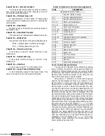
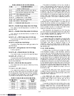
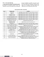
1.12.6 Controller Alarms (See Table 1-7)
The alarm philosophy balances the protection of the
refrigeration unit and that of the refrigerated cargo. The
action taken when an error is detected always considers
the survival of the cargo. Rechecks are made to confirm
an error actually exists. Some alarms requiring compres-
sor shutdown have time delays before and after to try to
keep the compressor operating. An example is a low
mains voltage. When the voltage drops over 25%, an
indication is given on the display, but the unit will
continue to run.
The red alarm light will illuminate for “20 series”
alarms only. If a detectable problem is found to exist, its
alarm code will be alternately displayed with the set point
on the left display.
To determine if other alarms exist or have existed,
the alarm list must be accessed. The alarm list will store
Downloaded from
Содержание 69NT40-489
Страница 1: ...Model 69NT40 489 T 259 Rev F Downloaded from ManualsNet com search engine ...
Страница 100: ...5 9 Figure 5 4 Electrical Wiring Diagram Model 69NT40 489 2 Sheet 2 of 2 Downloaded from ManualsNet com search engine ...
Страница 141: ...5 50 Figure 5 25 Electrical Schematic Model 69NT40 489 19 Sheet 1 of 2 Downloaded from ManualsNet com search engine ...
Страница 142: ...5 51 Figure 5 25 Electrical Schematic Model 69NT40 489 19 Sheet 2 of 2 Downloaded from ManualsNet com search engine ...
Страница 149: ...5 58 Figure 5 29 Electrical Schematic Models 69NT40 489 50 Sheet 1 of 2 Downloaded from ManualsNet com search engine ...
Страница 150: ...5 59 Figure 5 29 Electrical Schematic Models 69NT40 489 50 Sheet 2 of 2 Downloaded from ManualsNet com search engine ...
Страница 157: ...5 66 Figure 5 33 Electrical Schematic Models 69NT40 489 62 Sheet 1 of 2 Downloaded from ManualsNet com search engine ...
Страница 158: ...5 67 Figure 5 33 Electrical Schematic Models 69NT40 489 62 Sheet 2 of 2 Downloaded from ManualsNet com search engine ...
Страница 161: ...5 70 Figure 5 35 Electrical Schematic Models 69NT40 489 78 Sheet 1 of 2 Downloaded from ManualsNet com search engine ...
Страница 162: ...5 71 Figure 5 35 Electrical Schematic Models 69NT40 489 78 Sheet 2 of 2 Downloaded from ManualsNet com search engine ...
Страница 165: ...5 74 Figure 5 37 Electrical Schematic Models 69NT40 489 80 Sheet 1 of 2 Downloaded from ManualsNet com search engine ...
Страница 166: ...5 75 Figure 5 37 Electrical Schematic Models 69NT40 489 80 Sheet 2 of 2 Downloaded from ManualsNet com search engine ...
Страница 169: ...5 78 Figure 5 39 Electrical Schematic Models 69NT40 489 30 31 Sheet 1 of 2 Downloaded from ManualsNet com search engine ...
Страница 170: ...5 79 Figure 5 39 Electrical Schematic Models 69NT40 489 30 31 Sheet 2 of 2 Downloaded from ManualsNet com search engine ...

