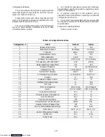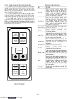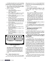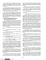
1-15
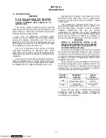
The operator may adjust the opening to increase or
decrease the air flow volume to meet the required air
flow.
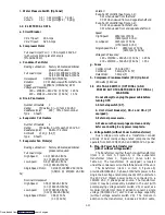
b. Air Sampling for Carbon Dioxide (CO
2
) Level
Loosen wing nuts and move cover until the arrow on
the cover is aligned with the “atmosphere sampling port”
label. Tighten wing nuts and attach a 3/8 tube to the
sampling tube.
If the internal atmosphere content has reached an
unacceptable level, the operator may adjust the cover
opening to meet the required air flow volume to ventilate
the container.
1.9
REMOTE MONITORING (OPTIONAL)
NOTE
Models with an in-range light, the light will be
illuminated if the container control air
temperature is within the tolerance selected.
Refer to section 1.12.5.
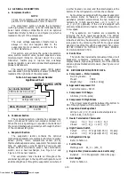
When the remote monitor is connected to the
remote monitoring receptacle, the following remote
circuits are energized.
Circuit
Function
Sockets B to A
Energizes remote cool light
Sockets C to A
Energizes remote defrost light
Sockets D to A
Energizes remote in-range light
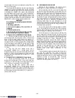
1.10 SUCTION SOLENOID VALVE
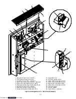
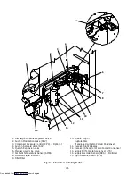
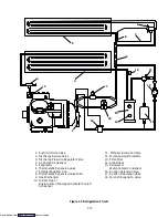
The suction solenoid valve, shown in Figure 1-3 is
controlled by the controller relay TS.
a. Operation
If set point is below ---10
_
C (+14
_
F) or ---5
_
C
(+23
_
F) optionally, the controller relay (TS) closes to
energize the suction solenoid valve (SSV). Once opened,
the refrigerant flow rate and unit cooling capacity is
increased.
If set point is above ---10
_
C (+14
_
F) or ---5
_
C
(+23
_
F) optionally, and the suction solenoid valve (SSV)
override is not activated, suction solenoid valve opens
during temperature pulldown period unless current
limiting or suction solenoid override restricts its use.
b. Suction Solenoid Override
This function restricts the opening of the suction
solenoid valve (SSV) under certain high ambient and/or
box temperature conditions. If the primary return sensor
(RTS) fails (AL56), the suction solenoid valve will not
open unless the ambient temperature is less than 10
_
C
(50
_
F). If the ambient sensor fails (AL57), the suction
solenoid valve will not be allowed to open until the return
air temperature is less than 1.67
_
C (35
_
F). If both the
ambient and return air (RTS) sensors fail, the suction
solenoid valve will not be allowed to open until at least
one of the sensors is repaired.
1.11 WATER-COOLED CONDENSER
(OPTIONAL)
The water-cooled condenser is used when cooling
water is available and heating the surrounding air is
objectionable, such as in a ship’s hold.
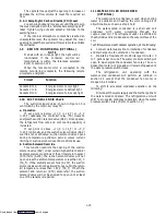
The water-cooled condenser is a shell and coil
condenser with water circulating through the
cupro-nickel coil. The refrigerant vapor is admitted to
the shell side and is condensed on the outer surface of the
coil.
To shift to water-cooled condenser operation, do the following:
a. Connect water supply line to inlet side of condenser
and discharge line to outlet side of condenser.
b. Maintain a flow rate of 11 to 26 liters per minute = 3
to 7 gallons per minute. The water pressure switch will
open to de-energize the condenser fan relay. The con-
denser fan motor will stop and will remain stopped until
the water pressure switch closes.
The refrigeration unit operating with the
water-cooled condenser will perform as outlined in
section 2.4 except that the condenser fan motor is
stopped in all modes.
To shift to air-cooled condenser operation, do the
following:
Disconnect the water supply and the discharge line to
the water-cooled condenser. The refrigeration unit will
shift to air-cooled condenser operation when the water
pressure switch closes. (Refer to section 1.3.)
Downloaded from
Содержание 69NT40-489
Страница 1: ...Model 69NT40 489 T 259 Rev F Downloaded from ManualsNet com search engine ...
Страница 100: ...5 9 Figure 5 4 Electrical Wiring Diagram Model 69NT40 489 2 Sheet 2 of 2 Downloaded from ManualsNet com search engine ...
Страница 141: ...5 50 Figure 5 25 Electrical Schematic Model 69NT40 489 19 Sheet 1 of 2 Downloaded from ManualsNet com search engine ...
Страница 142: ...5 51 Figure 5 25 Electrical Schematic Model 69NT40 489 19 Sheet 2 of 2 Downloaded from ManualsNet com search engine ...
Страница 149: ...5 58 Figure 5 29 Electrical Schematic Models 69NT40 489 50 Sheet 1 of 2 Downloaded from ManualsNet com search engine ...
Страница 150: ...5 59 Figure 5 29 Electrical Schematic Models 69NT40 489 50 Sheet 2 of 2 Downloaded from ManualsNet com search engine ...
Страница 157: ...5 66 Figure 5 33 Electrical Schematic Models 69NT40 489 62 Sheet 1 of 2 Downloaded from ManualsNet com search engine ...
Страница 158: ...5 67 Figure 5 33 Electrical Schematic Models 69NT40 489 62 Sheet 2 of 2 Downloaded from ManualsNet com search engine ...
Страница 161: ...5 70 Figure 5 35 Electrical Schematic Models 69NT40 489 78 Sheet 1 of 2 Downloaded from ManualsNet com search engine ...
Страница 162: ...5 71 Figure 5 35 Electrical Schematic Models 69NT40 489 78 Sheet 2 of 2 Downloaded from ManualsNet com search engine ...
Страница 165: ...5 74 Figure 5 37 Electrical Schematic Models 69NT40 489 80 Sheet 1 of 2 Downloaded from ManualsNet com search engine ...
Страница 166: ...5 75 Figure 5 37 Electrical Schematic Models 69NT40 489 80 Sheet 2 of 2 Downloaded from ManualsNet com search engine ...
Страница 169: ...5 78 Figure 5 39 Electrical Schematic Models 69NT40 489 30 31 Sheet 1 of 2 Downloaded from ManualsNet com search engine ...
Страница 170: ...5 79 Figure 5 39 Electrical Schematic Models 69NT40 489 30 31 Sheet 2 of 2 Downloaded from ManualsNet com search engine ...

