1-27
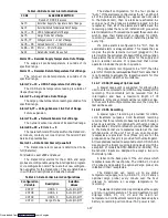
Alarm 63 --- Current Over Limit
Alarm 63 is triggered within the current limiting
system. If the compressor is ON and current limiting
procedures cannot maintain a current level below the
user selected limit, the current limit alarm is activated.
This alarm is a display alarm and is inactivated by
power cycling the unit, changing the current limit via the
code select Cd32, or if the SMV is allowed to open to
100% and the suction solenoid valve is allowed to open.
Alarm 64 --- Discharge Temperature Over Limit
Alarm 64 is triggered if the discharge temperature is
sensed greater than 154
_
C (310
_
F) for 3 continuous
minutes, or if it exceeds 177
_
C (350
_
F), or if the sensor is
out of range. This is a display alarm and has no associated
failure action.
Alarm 65 --- Discharge Pressure or Condenser
Pressure (CPC) Sensor Failure
Alarm 65 is triggered by a compressor discharge or
condenser pressure sensor reading outside the valid
range of 73.20 cm Hg (30 in Hg) to 32.34 Kg/cm
2
(460
psig). This is a display alarm and has no associated failure
action.
Alarm 66 --- Suction Pressure Sensor Failure
Alarm 66 is triggered by a suction pressure sensor
reading outside the valid range of 73.20 cm Hg (30 in Hg)
to 32.34 Kg/cm
2
(460 psig). This is a display alarm and has
no associated failure action.
Alarm 67 --- Humidity Sensor Failure
Alarm 67 is triggered by a humidity sensor reading
outside the valid range of 0% to 100% relative humidity.
If alarm 67 is active and the dehumidification mode
was previously activated, then it will be deactivated.
ERR # - Internal Microprocessor Failure
The controller performs self-check routines. if an
internal (electronic) failure occurs, an ERR #0---5 will
appear on the display. This is an indication the controller
needs to be replaced.
Entr stpt - Enter Setpoint (Press Arrow & Enter)
The Controller is prompting the operator to enter a
set point.
LO -
Low Mains Voltage (Change of function codes
Cd27-Cd33 disabled and no alarm stored.)
This message will be alternately displayed with the
set point whenever the mains voltage is less than 75% of
its proper voltage.
VENT
This message will be alternately displayed with the
set point whenever the CTD Controlled Atmosphere
(CA) option is in the VENT mode.
P-CA
This message will be alternately displayed with the
set point whenever the CTD Controlled Atmosphere
(CA) option is in the Pre-Trip mode.
NOTE
The left display of the Refrigeration Controller
will alternately display P-CA and set point for
units with the CTD Controlled Atmosphere
(CA) option (refer to Table 1-1).
1.13 PRE-TRIP DIAGNOSTICS
NOTE
The Refrigeration Controller will be locked-out
of Pre-Trip if the CTD Controlled Atmosphere
(CA) option (refer to Table 1-1) is in either the
Vent or Pre-Trip mode.
CAUTION
Pre-trip inspection should not be performed
with critical temperature cargoes in the
container.
Pre-trip Diagnostics is an independent mode which
will suspend the normal Control Mode activities when
initiated by the user. With pre-trip diagnostics, either all
the pre-trip tests can be executed in a defined sequence
(Auto Mode), or one of the pre-trip tests can be selected
to be executed (Manual Mode), based on the sequence of
key selections made.
a. Starting and Terminating Pre-Trip
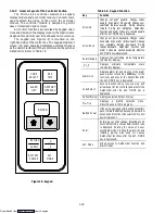
A Pre-trip selection menu is displayed by pressing the
PRE-TRIP key. This places the user into a test selection
menu. If no selection is made, the pre-trip menu selection
process will terminate automatically. Pre-Trip will termi-
nate if the VENT mode is selected on the CA Controller.
The user must scroll through the selection by pressing the
UP ARROW or DOWN ARROW keys, then pressing
the ENTER key when the selection is made. While the
tests are being executed, the user can terminate the
pre-trip mode by holding the PRE-TRIP key. The unit
will then resume normal operation. If the user decides to
terminate a test but remain at the test selection menu, the
user may press the UP ARROW key. When this is done
all machinery outputs will be de-energized and the test
selection menu will be displayed.
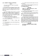
The pre-trip diagnostics may also be initiated via
communication, but when initiated will always attempt to
execute the entire battery of tests (auto mode).
b. Current Limiting During Pre-Trip
Throughout the duration of any pre-trip mode, the
Current Limit processing is active.
NOTE
When current limiting is initiated, the
compressor is immediately cycled through a
reliability enhancement algorithm (SMV is
cycled between 70% to 0%), to remove any
refrigerant trapped in the oil of the compressor.
This also happens during Pre-Trip tests P6-0 and
P6-4. For current limiting and P6-0 the algorithm
is 10 cycles long, and for P6-4 its 5 cycles long.
c. Test Codes
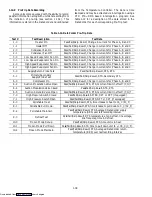
A detailed description of the pre-trip test codes is
listed in the following section, however, for a quick
reference list refer to Table 1-8.
Downloaded from
Содержание 69NT40-489
Страница 1: ...Model 69NT40 489 T 259 Rev F Downloaded from ManualsNet com search engine ...
Страница 100: ...5 9 Figure 5 4 Electrical Wiring Diagram Model 69NT40 489 2 Sheet 2 of 2 Downloaded from ManualsNet com search engine ...
Страница 141: ...5 50 Figure 5 25 Electrical Schematic Model 69NT40 489 19 Sheet 1 of 2 Downloaded from ManualsNet com search engine ...
Страница 142: ...5 51 Figure 5 25 Electrical Schematic Model 69NT40 489 19 Sheet 2 of 2 Downloaded from ManualsNet com search engine ...
Страница 149: ...5 58 Figure 5 29 Electrical Schematic Models 69NT40 489 50 Sheet 1 of 2 Downloaded from ManualsNet com search engine ...
Страница 150: ...5 59 Figure 5 29 Electrical Schematic Models 69NT40 489 50 Sheet 2 of 2 Downloaded from ManualsNet com search engine ...
Страница 157: ...5 66 Figure 5 33 Electrical Schematic Models 69NT40 489 62 Sheet 1 of 2 Downloaded from ManualsNet com search engine ...
Страница 158: ...5 67 Figure 5 33 Electrical Schematic Models 69NT40 489 62 Sheet 2 of 2 Downloaded from ManualsNet com search engine ...
Страница 161: ...5 70 Figure 5 35 Electrical Schematic Models 69NT40 489 78 Sheet 1 of 2 Downloaded from ManualsNet com search engine ...
Страница 162: ...5 71 Figure 5 35 Electrical Schematic Models 69NT40 489 78 Sheet 2 of 2 Downloaded from ManualsNet com search engine ...
Страница 165: ...5 74 Figure 5 37 Electrical Schematic Models 69NT40 489 80 Sheet 1 of 2 Downloaded from ManualsNet com search engine ...
Страница 166: ...5 75 Figure 5 37 Electrical Schematic Models 69NT40 489 80 Sheet 2 of 2 Downloaded from ManualsNet com search engine ...
Страница 169: ...5 78 Figure 5 39 Electrical Schematic Models 69NT40 489 30 31 Sheet 1 of 2 Downloaded from ManualsNet com search engine ...
Страница 170: ...5 79 Figure 5 39 Electrical Schematic Models 69NT40 489 30 31 Sheet 2 of 2 Downloaded from ManualsNet com search engine ...

