Section 4. Setting up Datalogger Networks
When the canvas is operating in this mode, the mouse cursor changes from a
hand to a jagged line. While in this mode, you can click on a station icon to
indicate the first device in the link. If that device can support a new link, a
small green “+” icon will appear in the center of that station icon and, as you
move the mouse, a green rubber-band line will follow the mouse cursor. At this
point, when you move the mouse cursor over the icon for another station that
has an interface that can be linked to the first station, another green “+” icon
will appear in the middle of that station. If the mouse cursor is hovering over a
station that does not have any compatible interface, a red “-” icon will appear
in the center of that station icon. You can complete the link by clicking the left
mouse button again, when the cursor is over another station with a small green
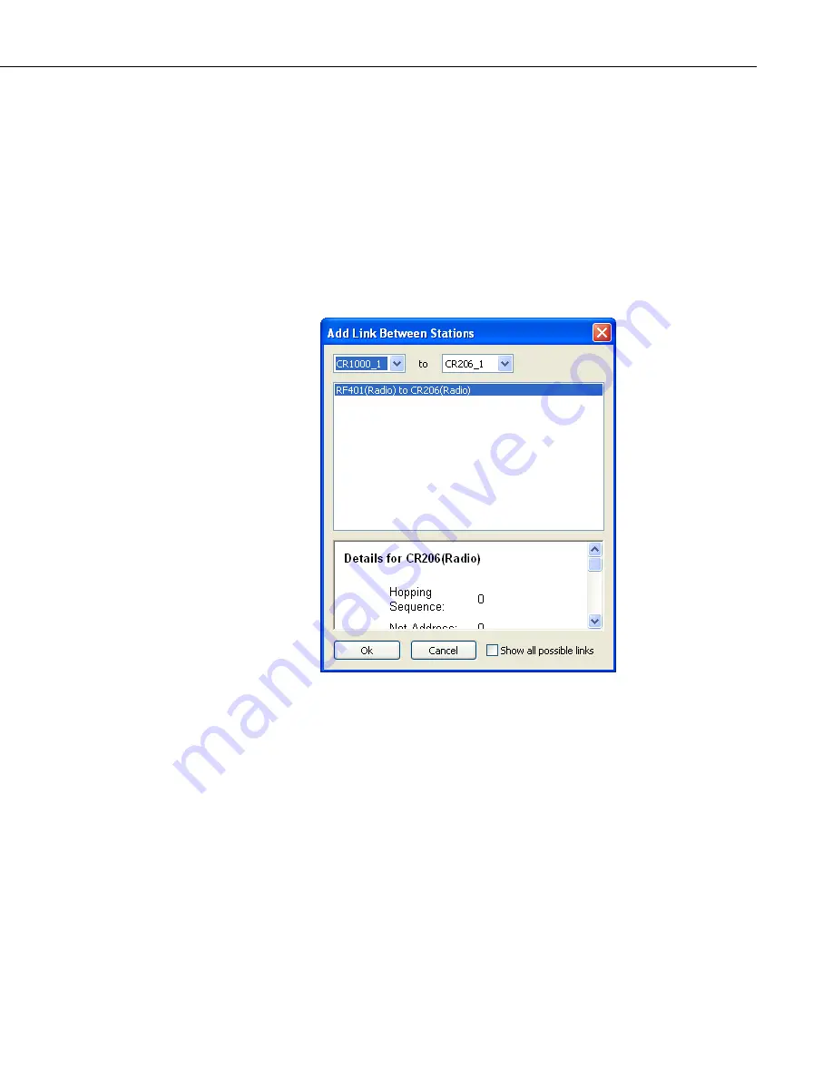
“+” icon indicating a compatible interface. At this point, the dialog shown
below will appear.
As with adding peripherals to stations, you must select the appropriate kind of
link. The dialog presents possible combinations between all the devices in both
stations. The list of link types is prioritized by the Network Planner, such that
the links considered the best are listed at the top. Note that the Network
Planner simplifies the task of selecting a link by hiding, by default, all of the
links except those that have the highest priority. You still have the option of
seeing all available choices by clicking on the
Show all possible links
check
box. The link will not be added until an appropriate link type is selected and
the
OK
button is pressed.
Station links are shown as lines between “connection points” on or around the
station icons. The end points of the link lines are small icons that represent the
nature of the link. An example of this is shown in the figure below of an RF401
based link.
4-67
Содержание LoggerNet
Страница 2: ......
Страница 30: ...Preface What s New in LoggerNet 4 xxvi...
Страница 32: ...Section 1 System Requirements 1 2...
Страница 44: ...Section 2 Installation Operation and Backup Procedures 2 12...
Страница 136: ...Section 4 Setting up Datalogger Networks 4 80...
Страница 227: ...Section 7 Creating and Editing Datalogger Programs 7 9...
Страница 298: ...Section 7 Creating and Editing Datalogger Programs 7 80...
Страница 402: ...Section 9 Automating Tasks with Task Master 9 12...
Страница 406: ...Section 9 Automating Tasks with Task Master 9 16...
Страница 450: ...Section 11 Utilities Installed with LoggerNet Admin and LoggerNet Remote 11 22...
Страница 454: ...Section 12 Optional Client Applications Available for LoggerNet 12 4...
Страница 462: ...Section 13 Implementing Advanced Communications Links 13 8...
Страница 482: ...Section 14 Troubleshooting Guide 14 20...
Страница 570: ...Appendix F Calibration and Zeroing F 16...
Страница 578: ...Appendix G Importing Files into Excel G 8...
Страница 579: ......


