50
[1.3 SETTINGS]
(SEt-)
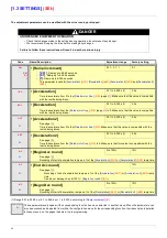
(1) In corresponds to the rated drive current indicated in the Installation Manual or on the drive nameplate.
Code
Name/Description
Adjustment range
Factory setting
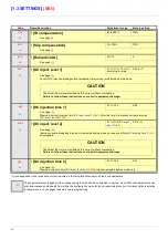
UFr
• [IR compensation]
25 to 200%
100%
*
See page
68
SLP
• [Slip compensation]
0 to 150%
100%
*
See page
68
dCF
• [Ramp divider]
0 to 10
4
*
See page
125
IdC
• [DC inject. level 1]
0.1 to 1.1 or 1.2 In (1)
according to rating
0.64 In (1)
*
See page
126
Level of DC injection braking current activated via logic input or selected as stop mode.
tdI
• [DC injection time 1]
0.1 to 30 s
0.5 s
*
See page
126
Maximum current injection time
[DC inject. level 1]
(IdC)
. After this time the injection current becomes
[DC inject. level 2]
(IdC2)
.
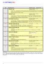
IdC2
• [DC inject. level 2]
0.1 In (1) to
[DC inject.
level 1]
(IdC)
0.5 In (1)
*
See page
126
Injection current activated by logic input or selected as stop mode, once period of time
[DC injection time 1]
(tdI)
has elapsed.
tdC
• [DC injection time 2]
0.1 to 30 s
0.5 s
*
See page
126
Maximum injection time
[DC inject. level 2]
(IdC2)
for injection selected as stop mode only.
*
These parameters only appear if the corresponding function has been selected in another menu. When the parameters can
also be accessed and adjusted from within the configuration menu for the corresponding function, their description is detailed
in these menus, on the pages indicated, to aid programming.
CAUTION
Check that the motor will withstand this current without overheating.
Failure to follow these instructions can result in equipment damage.
CAUTION
Check that the motor will withstand this current without overheating.
Failure to follow these instructions can result in equipment damage.
Содержание ER40-G
Страница 2: ......
Страница 21: ...21 The display flashes to indicate the presence of a fault ...
Страница 241: ......


