141
[1.7 APPLICATION FUNCT.]
(FUn-)
“Manual – Automatic” operation with PID
This function combines the PID regulator, the preset speeds and a manual reference. Depending on the state of the logic input, the speed
reference is given by the preset speeds or by a manual reference input via the PID function.
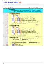
Manual reference (PIM)
• Analog inputs AI1 to AI4
• Frequency input
• Encoder
Predictive speed reference (FPI)
•
[AI1]
(AI1)
: Analog input
•
[AI2]
(AI2)
: Analog input
•
[AI3]
(AI3)
: Analog input, if VW3A3202 extension card has been inserted
•
[AI4]
(AI4)
: Analog input, if VW3A3202 extension card has been inserted
•
[RP]
(PI)
: Frequency input, if VW3A3202 extension card has been inserted
•
[Encoder]
(PG)
: Encoder input, if encoder card has been inserted
•
[HMI]
(LCC)
:
Graphic display terminal
•
[Modbus]
(Mdb)
: Integrated Modbus
•
[CANopen]
(CAn)
: Integrated CANopen
•
[Com. card]
(nEt)
: Communication card (if inserted)
•
[Prog. card]
(APP)
: Controller Inside card (if inserted)
Setting up the PID regulator
1.
1.
1.
1.
Configuration in PID mode
See the diagram on page
139
.
2.
2.
2.
2.
Perform a test in factory settings mode (in most cases, this will be sufficient).
To optimize the drive, adjust rPG or rIG gradually and independently and observe the effect on the PID feedback in relation to the
reference.
3.
3.
3.
3.
If the factory settings are unstable or the reference is incorrect
• Perform a test with a speed reference in Manual mode (without PID regulator) and with the drive on load for the speed range of the
system:
- In steady state, the speed must be stable and comply with the reference and the PID feedback signal must be stable.
- In transient state, the speed must follow the ramp and stabilize quickly, and the PID feedback must follow the speed.
If this is not the case, see the settings for the drive and/or sensor signal and wiring.
• Switch to PID mode.
• Set brA to no (no auto-adaptation of the ramp).
• Set the PID ramp (PrP) to the minimum permitted by the mechanism without triggering an ObF fault.
• Set the integral gain (rIG) to minimum.
• Leave the derivative gain (rdG) at 0.
• Observe the PID feedback and the reference.
• Switch the drive ON/OFF a number of times or vary the load or reference rapidly a number of times.
• Set the proportional gain (rPG) in order to ascertain the best compromise between response time and stability in transient phases
(slight overshoot and 1 to 2 oscillations before stabilizing).
• If the reference varies from the preset value in steady state, gradually increase the integral gain (rIG), reduce the proportional gain
(rPG) in the event of instability (pump applications), find a compromise between response time and static precision (see diagram).
• Lastly, the derivative gain may permit the overshoot to be reduced and the response time to be improved, although this will make
it more difficult to obtain a compromise in terms of stability, as it depends on 3 gains.
• Perform in-production tests over the whole reference range.
Содержание ER40-G
Страница 2: ......
Страница 21: ...21 The display flashes to indicate the presence of a fault ...
Страница 241: ......


