174
[1.8 FAULT MANAGEMENT]
(FLt-)
Code
Name/Description
Adjustment range
Factory setting
PtC-
•
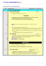
[PTC MANAGEMENT]
PtCL
• [LI6 = PTC probe]
[No]
(nO)
nO
AS
rdS
rS
Can be accessed if switch SW2 on the control card is set to PTC.
-
[No]
(nO)
: Not used
-
[Always]
(AS)
: “PTC probe” faults are monitored permanently, even if the power supply is not connected
(as long as the control remains connected to the power supply).
-
[Power ON]
(rdS)
: “PTC probe” faults are monitored while the drive power supply is connected.
-
[Motor ON]
(rS)
: “PTC probe” faults are monitored while the motor power supply is connected.
PtC1
• [PTC1 probe]
[No]
(nO)
nO
AS
rdS
rS
Can be accessed if a VW3A3201 option card has been inserted.
-
[No]
(nO)
: Not used
-
[Always]
(AS)
: “PTC probe” faults are monitored permanently, even if the power supply is not connected
(as long as the control remains connected to the power supply).
-
[Power ON]
(rdS)
: “PTC probe” faults are monitored while the drive power supply is connected.
-
[Motor ON]
(rS)
: “PTC probe” faults are monitored while the motor power supply is connected.
PtC2
• [PTC2 probe]
[No]
(nO)
nO
AS
rdS
rS
Can be accessed if a VW3A3202 option card has been inserted.
-
[No]
(nO)
: Not used
-
[Always]
(AS)
: “PTC probe” faults are monitored permanently, even if the power supply is not connected
(as long as the control remains connected to the power supply).
-
[Power ON]
(rdS)
: “PTC probe” faults are monitored while the drive power supply is connected.
-
[Motor ON]
(rS)
: “PTC probe” faults are monitored while the motor power supply is connected.
rSt-
•
[FAULT RESET]
rSF
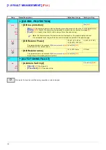
• [Fault reset]
[LI4]
(LI4)
nO
LI1
-
-
C101
-
-
-
Cd00
-
Manual fault reset
-
[No]
(nO)
: Function inactive
-
[LI1]
(LI1)
to
[LI6]
(LI6)
-
[LI7]
(LI7)
to
[LI10]
(LI10)
: If VW3A3201 logic I/O card has been inserted
-
[LI11]
(LI11)
to
[LI14]
(LI14)
: If VW3A3202 extended I/O card has been inserted
-
[C101]
(C101)
to
[C115]
(C115)
: With integrated Modbus in [I/O profile] (IO)
-
[C201]
(C201)
to
[C215]
(C215)
: With integrated CANopen in [I/O profile] (IO)
-
[C301]
(C301)
to
[C315]
(C315)
: With a communication card in [I/O profile] (IO)
-
[C401]
(C401)
to
[C415]
(C415)
: With a Controller Inside card in [I/O profile] (IO)
-
[CD00]
(Cd00)
to
[CD13]
(Cd13)
: In [I/O profile] (IO) can be switched with possible logic inputs
-
[CD14]
(Cd14)
to
[CD15]
(Cd15)
: In [I/O profile] (IO) can be switched without logic inputs
Faults are reset when the assigned input or bit changes to 1, if the cause of the fault has disappeared.
The STOP/RESET button on the graphic display terminal performs the same function.
See pages
220
to
223
for the list of faults that can be reset manually.
Содержание ER40-G
Страница 2: ......
Страница 21: ...21 The display flashes to indicate the presence of a fault ...
Страница 241: ......


