43
[1.2 MONITORING]
(SUP-)
With integrated display terminal
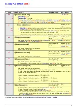
This menu can be used to display the drive inputs, states and internal values.
Code
Name/Description
Adjustment range
Factory setting
IOM-
I/O MAP
LIA-
•
Logic input functions
L1A
to
L14A
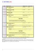
Can be used to display the functions assigned to each input. If no functions have been assigned, nO is
displayed.
Use the
and
arrows to scroll through the functions. If a number of functions have been assigned
to the same input, check that they are compatible.
LIS1
•
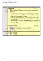
State of logic inputs LI1 to LI8
Can be used to visualize the state of logic inputs LI1 to LI8
(display segment assignment: high = 1, low = 0)
Example above: LI1 and LI6 are at 1; LI2 to LI5, LI7 and LI8 are at 0.
LIS2
•
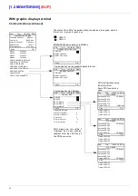
State of logic inputs LI9 to LI14 and Power Removal
Can be used to visualize the state of logic inputs LI19to LI14 and PR (Power Removal)
(display segment assignment: high = 1, low = 0)
Example above: LI9 and LI14 are at 1, LI10 to LI13 are at 0 and PR (Power Removal) is at 1.
AIA-
•
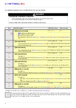
Analog input functions
AI1A
AI2A
AI3A
AI4A
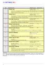
Can be used to display the functions assigned to each input. If no functions have been assigned, nO is
displayed. Use the
and
arrows to scroll through the functions. If a number of functions have been
assigned to the same input, check that they are compatible.
State 1
State 0
LI1 LI2 LI3 LI4 LI5 LI6 LI7 LI8
State 1
State 0
LI9 LI10 LI11 LI12 LI13 LI14 PR
Содержание ER40-G
Страница 2: ......
Страница 21: ...21 The display flashes to indicate the presence of a fault ...
Страница 241: ......


