170
Options List
C.17.5
Performance
Accuracy:
±
50 ns from 1 PPS, max (
−
10 ns, typical)
Jitter:
1 ns rms, max. pulse to pulse (guaranteed by design, not production tested)
C.17.6
Outputs
Connectors:
Four, BNC 50-ohm, configurable
Signals:
Normal Polarity COMTRADE Sample Rate, 50% Duty Cycle
Complemented COMTRADE Sample Rate, 50% Duty Cycle
All 21 Other Signals Available in the 1088B Clock
C.17.7
Drive Capability
Digital:
5V CMOS Buffer, 50 Ohms Impedance
Analog:
Opamp Buffer, 600 Ohms Impedance
C.17.8
Setup
Setup Menu
The SETUP menu allows the user to modify internal operating firmware parameters within both
the Model 1084A/B/C and Model 1088A/B. The SETUP menu can be easily accessed from the
front panel keyboard.
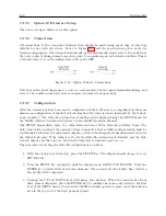
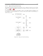
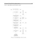
Figure C.23 illustrates the Option 23 SETUP menu for the standard Model 1088A/B SETUP menu.
However, for clarity only Option 23 is described.
RS-232C Commands
Option 23 can also be configured via the RS-232C interface using one of the following commands:
Configure Option 23
Command:
m:rCA, m:rCB
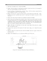
m:rCA configures Option 23 to operate correctly from Option Slot A in the Model 1084A/B/C, or
from the Model 1088B. m:rCB configures Option 23 to operate correctly from Option Slot B from
the Model 1088B only.
Response:
C
Where:
m
0 = 50 Hz
1 = 60 Hz
r
Содержание 1088A
Страница 4: ...iv ...
Страница 6: ...vi ...
Страница 18: ...xviii LIST OF FIGURES ...
Страница 23: ...1 4 Attaching Rack Mount Ears to 1088A B Series Clocks 3 Figure 1 2 Attaching Rack Mount Ears ...
Страница 24: ...4 Unpacking the Clock ...
Страница 32: ...12 Front and Rear Panels ...
Страница 38: ...18 Connecting Inlet Power Input and Output Signals ...
Страница 41: ...4 1 GPS Antenna Installation 21 Figure 4 2 Antenna Mounting Bracket Figure 4 3 Antenna Mounting with AS0044600 ...
Страница 46: ...26 GPS Antenna and Cable Information ...
Страница 48: ...28 Setting Internal Jumpers Figure 5 1 Model 1088B Main Board ...
Страница 76: ...56 The Setup Menus ...
Страница 112: ...92 Serial Communication and Command Set ...
Страница 127: ...B 4 Physical Dimensions 107 Figure B 1 Suggested Mounting of the AS0094500 Surge Arrester ...
Страница 128: ...108 Using Surge Arresters ...
Страница 137: ...C 5 Option 04 Parallel BCD Output 117 C 5 2 Option 04 Firmware Setup Figure C 2 Option 04 Firmware Setup ...
Страница 145: ...C 5 Option 04 Parallel BCD Output 125 Figure C 4 Option 04 Output Jumper Settings ...
Страница 146: ...126 Options List Figure C 5 Option 04 Board Layout and Jumper Locations ...
Страница 165: ...C 12 Option 17 Parallel BCD Output and Second RS 232 Port 145 Figure C 11 Option 17 Output Jumper Settings ...
Страница 166: ...146 Options List Figure C 12 Option 17 Board Layout and Jumper Locations ...
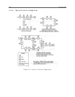
Страница 176: ...156 Options List C 14 5 Typical Network Configuration Figure C 15 Option 18 Network Configuration ...
Страница 187: ...C 16 Option 20A Four Fiber Optic Outputs 167 Figure C 22 Option 20A Jumper Locations ...
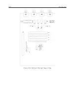
Страница 194: ...174 Options List Figure C 24 Option 23 Internal Jumper Setup ...
Страница 196: ...176 Options List Figure C 25 Option 27 Jumper Locations ...
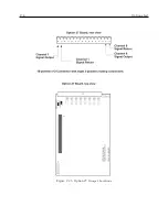
Страница 214: ...194 Options List Figure C 28 Option 29 Connector Signal Locations ...
Страница 270: ...250 Options List ...

