Chapter 9
Serial Communication and Command
Set
9.1
Introduction
The Model 1088B has one main RS-232C port, and one optional RS-232C port (Option 17A). These
are labeled RS-232C and Option RS-232C. When viewing the rear panel, the main port is nearest
the antenna connector and the optional port is to the left of the Standard I/O connectors.
It is
important to note that neither the standard RS-232, nor the Option RS-232C port have an RS-485
function and neither RS-232C ports use flow control
.
Use the two serial ports interchangeably for separate functions. You may wish to interrogate the
clock on one port for basic information (i.e to configure something) and at the same time be able
to have the second serial port broadcasting a specific time code to a meter. While most recent
substation equipment has standardized on the IRIG-B time code, some devices are designed to
receive ASCII data through the serial port. Another common serial-port function is to connect a
digital wall display to indicate the time.
9.2
Command Set
This section provides information for controlling and communicating with these clocks via the
RS-232C serial interface. All of the RS-232C commands are functionally grouped into similar
categories. For example, Section 9.2.1 lists all of the commands used to both set and retrieve the
date and time in one of the standard formats.
Each command name and syntax is highlighted in bold at the beginning of each definition. De-
tailed information used to interpret the commands and responses follows each command heading.
Sometimes the command is very short, such as the command to return the Local Time: TL. Other
commands require a prefix or suffix with the letter command to specify them, such as to broad-
cast: Bn, where n equals an integer specifying the broadcast. For example, the command to start
the ASCII Standard broadcast string at a rate of once per second, on Local time, from the main
RS-232C port is B1.
Содержание 1088A
Страница 4: ...iv ...
Страница 6: ...vi ...
Страница 18: ...xviii LIST OF FIGURES ...
Страница 23: ...1 4 Attaching Rack Mount Ears to 1088A B Series Clocks 3 Figure 1 2 Attaching Rack Mount Ears ...
Страница 24: ...4 Unpacking the Clock ...
Страница 32: ...12 Front and Rear Panels ...
Страница 38: ...18 Connecting Inlet Power Input and Output Signals ...
Страница 41: ...4 1 GPS Antenna Installation 21 Figure 4 2 Antenna Mounting Bracket Figure 4 3 Antenna Mounting with AS0044600 ...
Страница 46: ...26 GPS Antenna and Cable Information ...
Страница 48: ...28 Setting Internal Jumpers Figure 5 1 Model 1088B Main Board ...
Страница 76: ...56 The Setup Menus ...
Страница 112: ...92 Serial Communication and Command Set ...
Страница 127: ...B 4 Physical Dimensions 107 Figure B 1 Suggested Mounting of the AS0094500 Surge Arrester ...
Страница 128: ...108 Using Surge Arresters ...
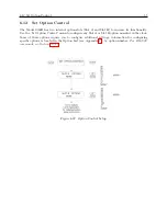
Страница 137: ...C 5 Option 04 Parallel BCD Output 117 C 5 2 Option 04 Firmware Setup Figure C 2 Option 04 Firmware Setup ...
Страница 145: ...C 5 Option 04 Parallel BCD Output 125 Figure C 4 Option 04 Output Jumper Settings ...
Страница 146: ...126 Options List Figure C 5 Option 04 Board Layout and Jumper Locations ...
Страница 165: ...C 12 Option 17 Parallel BCD Output and Second RS 232 Port 145 Figure C 11 Option 17 Output Jumper Settings ...
Страница 166: ...146 Options List Figure C 12 Option 17 Board Layout and Jumper Locations ...
Страница 176: ...156 Options List C 14 5 Typical Network Configuration Figure C 15 Option 18 Network Configuration ...
Страница 187: ...C 16 Option 20A Four Fiber Optic Outputs 167 Figure C 22 Option 20A Jumper Locations ...
Страница 194: ...174 Options List Figure C 24 Option 23 Internal Jumper Setup ...
Страница 196: ...176 Options List Figure C 25 Option 27 Jumper Locations ...
Страница 214: ...194 Options List Figure C 28 Option 29 Connector Signal Locations ...
Страница 270: ...250 Options List ...

