8.2 Event Inputs
67
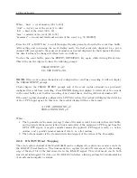
Where: “nnn” = event number (001 to 200)
“ddd” = day of year of the event (1 to 366)
“hh” = hour of the event (00 to 23)
“mm” = minute of the event (00 to 59)
“ss.sssssss” = second and fractional seconds of the event (e.g. 59.9999999)
Press the UP or DOWN key to scroll through all events presently stored in the event time buffer.
After exiting and re-entering the event display mode, the first event data displayed for a given
channel will correspond to the same event number as was last displayed for that channel. However,
the data itself may be changed if it has been overwritten.
To clear the event buffer, press the EVENT/DEVIATION key again, while viewing Event data.
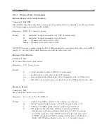
This will cause the display to issue the following prompt:
CLEAR EVENT (A)?
UP=YES DOWN=NO
NOTE:
If the event capture channel is not configured for event time recording, it will not display
the CLEAR EVENT prompt.
Clocks display the CLEAR EVENT prompt only if the event capture channel was previously
configured for event time recording. Press ENTER during this display to delete all of the records
in the event buffer, and to allow recording of new event times, starting with event number 001.
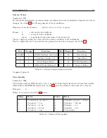
If the event capture channel is configured for 1–PPS Deviation, the readout will display the deviation
of the 1–PPS input signal. In this case, the readout display will have the format:
A 1 PPS
±
XXXXX.XX
µ
S
SIGMA: XXXXX.XX
µ
S
Where:
1. The top number is the mean (average) value of the most recent 16 records in the event buffer,
and represents the mean deviation (in microseconds) of the measured 1–PPS signal from the
GPS 1–PPS signal. A negative number means the applied 1–PPS signal is early, i.e. before
on-time, and a positive number means it is late, i.e. after on-time.
2. The bottom number is the standard deviation (sigma) of the values of the 16 samples.
8.2.8
RS-232C Event Trapping
The event capture channel of the Model 1088B can be configured to capture one or more events via
the RS-232C Serial Interface. The time mark for a captured event will correspond to the leading
edge of the start bit of the first character in the RS-232C signal. This event mode can be both
armed and interrogated for data over the RS-232C interface, allowing automated synchronization
of an external computer or system.
Содержание 1088A
Страница 4: ...iv ...
Страница 6: ...vi ...
Страница 18: ...xviii LIST OF FIGURES ...
Страница 23: ...1 4 Attaching Rack Mount Ears to 1088A B Series Clocks 3 Figure 1 2 Attaching Rack Mount Ears ...
Страница 24: ...4 Unpacking the Clock ...
Страница 32: ...12 Front and Rear Panels ...
Страница 38: ...18 Connecting Inlet Power Input and Output Signals ...
Страница 41: ...4 1 GPS Antenna Installation 21 Figure 4 2 Antenna Mounting Bracket Figure 4 3 Antenna Mounting with AS0044600 ...
Страница 46: ...26 GPS Antenna and Cable Information ...
Страница 48: ...28 Setting Internal Jumpers Figure 5 1 Model 1088B Main Board ...
Страница 76: ...56 The Setup Menus ...
Страница 112: ...92 Serial Communication and Command Set ...
Страница 127: ...B 4 Physical Dimensions 107 Figure B 1 Suggested Mounting of the AS0094500 Surge Arrester ...
Страница 128: ...108 Using Surge Arresters ...
Страница 137: ...C 5 Option 04 Parallel BCD Output 117 C 5 2 Option 04 Firmware Setup Figure C 2 Option 04 Firmware Setup ...
Страница 145: ...C 5 Option 04 Parallel BCD Output 125 Figure C 4 Option 04 Output Jumper Settings ...
Страница 146: ...126 Options List Figure C 5 Option 04 Board Layout and Jumper Locations ...
Страница 165: ...C 12 Option 17 Parallel BCD Output and Second RS 232 Port 145 Figure C 11 Option 17 Output Jumper Settings ...
Страница 166: ...146 Options List Figure C 12 Option 17 Board Layout and Jumper Locations ...
Страница 176: ...156 Options List C 14 5 Typical Network Configuration Figure C 15 Option 18 Network Configuration ...
Страница 187: ...C 16 Option 20A Four Fiber Optic Outputs 167 Figure C 22 Option 20A Jumper Locations ...
Страница 194: ...174 Options List Figure C 24 Option 23 Internal Jumper Setup ...
Страница 196: ...176 Options List Figure C 25 Option 27 Jumper Locations ...
Страница 214: ...194 Options List Figure C 28 Option 29 Connector Signal Locations ...
Страница 270: ...250 Options List ...


