200
Options List
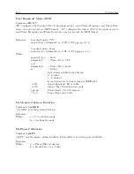
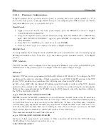
lowercase ‘x’ characters to the NTP Server. These characters must all be sent within one second
to start configuration mode.
NOTE:
The easiest way to enter configuration mode is to hold down the ‘x’ key at the terminal
(emulation) and then powering the NTP Server. This will ensure that the x characters will arrive
in time.
C.21.4
General Configuration
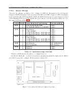
After entering the configuration mode (confirmed with
<
CR
>
), the parameters can be changed;
confirm default values with the enter key. Leaving the setup mode after selecting function 9 stores
all parameters in a nonvolatile memory, and the NTP server resets.
C.21.5
Basic Parameters
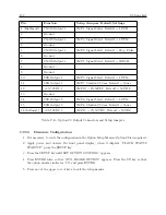
To change the basic parameters, type ‘0’. The following values can be set/changed:
Ethernet Interface:
Set to (N).
IP Address:
The IP address must be set to a unique value in your network. If the NTP Server is
set to an address, which is already in use, it will display an error code with the LEDs (see “LED
Status”) and will not connect to the network.
Gateway IP Address:
The router/gateway address is needed to communicate to other LAN
segments. The default gateway must be set to address the router that connects these segments.
This address must be within the local network. If in doubt, consult the network administrator.
Net mask:
A net mask defines how many bits from the IP address are to be taken as the network
section and how many bits are to be taken as the host section (reminder: Standard class A 8/24
[net/host], class B 16/16, class C 24/8 bits). If set to 0, the standard appropriate net mask for the
actual IP address is used. The NTS prompts for the number of host bits, and then calculates the
net mask. It is shown in standard format “255.255.xxx.xxx” when parameters are displayed.
Telnet Config Password:
The Telnet configuration password can be set to disable unauthorized
access to the setup menu through a Telnet connection to the setup port (9999). For the setup
through the serial port, it is not necessary to enter the password. The controller can be configured
over a Telnet connection to port 9999 (assuming the network parameters are set correctly and the
NTS is connected to the network).
C.21.6
NTP Server Parameters
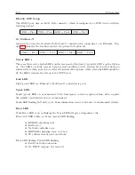
The network operations of the server are controlled by various parameters.
Antenna Type:
Set type to 6=GPS/Arbiter
UDP-Port:
The UDP port selects the port number for the NTP proprietary protocol.
Send Block Every n Minutes:
This parameter determines how often the data block should be
sent.
Send UDP-Broadcast:
If the time information should be sent to all devices connected to this
LAN (broadcast), set this parameter to “Y” = yes.
UDP-Target Address:
This parameter determines the target addresses to which the data block
should be sent. The data block can be sent over a Gateway or other devices to another part of the
network. The maximum number of defined addresses is eight. NTP and UDP/time port numbers
Содержание 1088A
Страница 4: ...iv ...
Страница 6: ...vi ...
Страница 18: ...xviii LIST OF FIGURES ...
Страница 23: ...1 4 Attaching Rack Mount Ears to 1088A B Series Clocks 3 Figure 1 2 Attaching Rack Mount Ears ...
Страница 24: ...4 Unpacking the Clock ...
Страница 32: ...12 Front and Rear Panels ...
Страница 38: ...18 Connecting Inlet Power Input and Output Signals ...
Страница 41: ...4 1 GPS Antenna Installation 21 Figure 4 2 Antenna Mounting Bracket Figure 4 3 Antenna Mounting with AS0044600 ...
Страница 46: ...26 GPS Antenna and Cable Information ...
Страница 48: ...28 Setting Internal Jumpers Figure 5 1 Model 1088B Main Board ...
Страница 76: ...56 The Setup Menus ...
Страница 112: ...92 Serial Communication and Command Set ...
Страница 127: ...B 4 Physical Dimensions 107 Figure B 1 Suggested Mounting of the AS0094500 Surge Arrester ...
Страница 128: ...108 Using Surge Arresters ...
Страница 137: ...C 5 Option 04 Parallel BCD Output 117 C 5 2 Option 04 Firmware Setup Figure C 2 Option 04 Firmware Setup ...
Страница 145: ...C 5 Option 04 Parallel BCD Output 125 Figure C 4 Option 04 Output Jumper Settings ...
Страница 146: ...126 Options List Figure C 5 Option 04 Board Layout and Jumper Locations ...
Страница 165: ...C 12 Option 17 Parallel BCD Output and Second RS 232 Port 145 Figure C 11 Option 17 Output Jumper Settings ...
Страница 166: ...146 Options List Figure C 12 Option 17 Board Layout and Jumper Locations ...
Страница 176: ...156 Options List C 14 5 Typical Network Configuration Figure C 15 Option 18 Network Configuration ...
Страница 187: ...C 16 Option 20A Four Fiber Optic Outputs 167 Figure C 22 Option 20A Jumper Locations ...
Страница 194: ...174 Options List Figure C 24 Option 23 Internal Jumper Setup ...
Страница 196: ...176 Options List Figure C 25 Option 27 Jumper Locations ...
Страница 214: ...194 Options List Figure C 28 Option 29 Connector Signal Locations ...
Страница 270: ...250 Options List ...


