C.22 Option 34: NTP/PTP Server
207
Viewing the IP Address on the Front Panel
The front panel will indicate the IP address of each port provided a network cable is connected.
Press the SYSTEM key until reaching OPTION STATUS OPTION 34 and press the ENTER key.
Use the UP/DOWN keys to scroll to any network-related information, such as the connection (Link)
status, the IP address or hardware address. Press any upper key to exit.
Important Configuration Change Notes
Certain configuration changes will cause you to lose the web interface connection. These configu-
ration changes include:
1. changing from HTTP to HTTPS
2. changing a Network configuration
3. changing a System configuration on the port which you are connected.
If you are making changes to another port, the web interface connection will not be dropped. To
make the changes persist, you will need to re-log in to the web interface using the new setting(s). To
lose changes, reboot the clock. After making any changes to the NTP service, you may experience
a delay of up to five minutes for the NTP service to start.
Startup Page: System
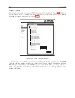
When logging in to the Option 34 using the web interface, the opening screen should be the System
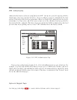
Status information page. This provides an overview of the operation of the Option 34. Figure C.31
illustrates the opening System Status page.
Option 34 Network Time Module
NTP
PTP
Clock
Network
Support
Logout
System
System Time 07 Apr 2014 15:44:00 PDT
System Time Offset -108us
Time Quality Locked
NTP Running
PTP Enabled (Running)
SNMP Enabled (Running)
SNMP Traps Enabled
Status
Configure
Password Update Reboot
Temperature 27.8
o
C
Figure C.31: Startup Page
Содержание 1088A
Страница 4: ...iv ...
Страница 6: ...vi ...
Страница 18: ...xviii LIST OF FIGURES ...
Страница 23: ...1 4 Attaching Rack Mount Ears to 1088A B Series Clocks 3 Figure 1 2 Attaching Rack Mount Ears ...
Страница 24: ...4 Unpacking the Clock ...
Страница 32: ...12 Front and Rear Panels ...
Страница 38: ...18 Connecting Inlet Power Input and Output Signals ...
Страница 41: ...4 1 GPS Antenna Installation 21 Figure 4 2 Antenna Mounting Bracket Figure 4 3 Antenna Mounting with AS0044600 ...
Страница 46: ...26 GPS Antenna and Cable Information ...
Страница 48: ...28 Setting Internal Jumpers Figure 5 1 Model 1088B Main Board ...
Страница 76: ...56 The Setup Menus ...
Страница 112: ...92 Serial Communication and Command Set ...
Страница 127: ...B 4 Physical Dimensions 107 Figure B 1 Suggested Mounting of the AS0094500 Surge Arrester ...
Страница 128: ...108 Using Surge Arresters ...
Страница 137: ...C 5 Option 04 Parallel BCD Output 117 C 5 2 Option 04 Firmware Setup Figure C 2 Option 04 Firmware Setup ...
Страница 145: ...C 5 Option 04 Parallel BCD Output 125 Figure C 4 Option 04 Output Jumper Settings ...
Страница 146: ...126 Options List Figure C 5 Option 04 Board Layout and Jumper Locations ...
Страница 165: ...C 12 Option 17 Parallel BCD Output and Second RS 232 Port 145 Figure C 11 Option 17 Output Jumper Settings ...
Страница 166: ...146 Options List Figure C 12 Option 17 Board Layout and Jumper Locations ...
Страница 176: ...156 Options List C 14 5 Typical Network Configuration Figure C 15 Option 18 Network Configuration ...
Страница 187: ...C 16 Option 20A Four Fiber Optic Outputs 167 Figure C 22 Option 20A Jumper Locations ...
Страница 194: ...174 Options List Figure C 24 Option 23 Internal Jumper Setup ...
Страница 196: ...176 Options List Figure C 25 Option 27 Jumper Locations ...
Страница 214: ...194 Options List Figure C 28 Option 29 Connector Signal Locations ...
Страница 270: ...250 Options List ...


